Table of Contents

Subscribe to Our Youtube Channel
Related Manuals for HWM PermaNet+


Summary of Contents for HWM PermaNet+
- Page 1 User Guide: PermaNet+ with Hydrophone Installation and Setup. Warning: This manual contains important safety and operating information. Please read, understand, and follow the instructions in the manual. MAN-148-0007-A January 2022.
-
Page 2: Table Of Contents
TABLE OF CONTENTS Introduction, Background and Support of Product............4 Safety Considerations ....................4 Background ........................ 4 About PermaNET+ ..................... 4 Documentation and Support of Product ..............5 Operating Temperature .................... 5 Unpacking ........................6 Overview and preparation for use ................... 7 PermaNet+ Logger –... - Page 3 Install logger ......................22 Connection of Hydrophone to a fitting ..............23 Activate logger and confirm settings ..............26 Installing the antenna and testing cellular communications ....... 26 Antenna Options and Installation Guidelines ............... 27 Antenna Options ...................... 27 6.1.1 Monopole ......................
-
Page 4: Introduction, Background And Support Of Product
NTRODUCTION ACKGROUND AND UPPORT OF RODUCT Thank you for choosing a HWM device. We trust it will provide you with many years of service. 1.1 S AFETY ONSIDERATIONS Before continuing, carefully read and follow the information in the “Safety Warnings and Approvals Information”... -
Page 5: Documentation And Support Of Product
HWM provides support of the logger devices by means of our customer support webpages: https://www.hwmglobal.com/help-and-downloads/ Should you have any questions that are not covered by this manual or the system’s online help, please contact the HWM Technical Support team on +44 (0) 1633 489479, or email cservice@hwm-water.com 1.5 O... -
Page 6: Unpacking
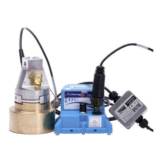
1.6 U NPACKING As you unpack your new PermaNet+ logger and Hydrophone, please confirm that you have the following parts: PermaNet+ data logger. • Cable (with in-line amplifier box) for connecting the Hydrophone to the • PermaNet+ logger. Hydrophone unit. •... -
Page 7: Overview And Preparation For Use
The PermaNet+ product family includes models with an interface for the HWM Hydrophone unit. They are (when the antenna and sensor are attached) of a waterproof construction, being designed to be permanently installed around a water network, listening for leaking pipes. -
Page 8: Cellular Communications And Sim-Card
APTOP COMPUTER The logger includes a serial communications interface. This enables the user to communicate with the logger during installation and make on-site tests. Communication requires the attachment of a HWM communications cable and also the HWM “IDT ” software. -
Page 9: System Overview
A Laptop PC (with Microsoft Windows). • The laptop PC can (with HWM software installed and a suitable comms cable) provide a Graphical User Interface for the user, giving access to set up and test the logger. -
Page 10: Datagate
This section introduces the terminology that is used by DataGate and the IDT… The destination of PermaNet+ logger data is usually the DataGate system, provided by HWM. DataGate and PermaNETWeb web-pages are the main administration and viewing portals for logger and site data. -
Page 11: Ways To Set The Logger Configuration
area have loggers that have produced sound recordings at precisely the same time, the approximate location of the suspect leak can often be found, using a process called Leak Localisation / Correlation. Note: Always use a ground microphone to confirm a leak location prior to commencing repair works. - Page 12 Deploy the loggers to sites without any checks being made (i.e., skip some of the • steps listed as optional). A follow-up team is then sent to selected sites to improve those that have communication problems. Installation consists of several steps… Installation sites must be selected.
-
Page 13: Logger Activation Process (For First-Time Use)
IDT (PC version) and its user-guide can be downloaded from the HWM Customer Support website, or from the following webpage: https://www.hwmglobal.com/idt-support/ (Note: The user has to be registered by HWM and have a password to gain access). Refer to the IDT User-guide for information on how to install and use the tool. -
Page 14: Communicating With The Permanet+ Logger
LOGGER 3.2.1 Connecting the comms cable To communicate with the unit a communications cable is required. This is a “Y-cable” (3 connectors). (HWM cable part-number: CABA9349/P). One connector is for temporary connection of the Hydrophone. • One connector is for the logger (plugs into the “LNS & Comms” interface). -
Page 15: Loading Logger Settings Into Idt
3.2.2 Loading Logger settings into IDT Click ‘Read Device’. A progress bar will show across the top of the page. When completed, an information box will appear stating ‘Device Read Success’. Click “OK” to clear the box. The IDT-PC program has now read a copy of the unit’s program (settings) into the “current program”... -
Page 16: Displaying Logger Device Information / Logging Status
Note: Please refer to the IDT (PC version) user-guide. The above user-guide is written primarily for a multi-purpose data logger, however many of the IDT functions and settings are common to the PermaNet+ device. Where this is so, they will only be mentioned briefly in this guide. The PermaNet+ operation is not that of a general-purpose data logger but has its own specialised leak determination programs. -
Page 17: Configuring The Permanet+ Logger
ONFIGURING THE ERMA LOGGER 4.1 S ETUP OF REGULAR REPETITIVE ERMA PROGRAM To configure the logger, first select the Setup tab in IDT. The IDT display is adaptive in behaviour and shows information and controls which change depending on previous selections / de-selections. - Page 18 There are 2 panels that determine the primary method the logger uses to send data when it calls into the server. They include a setting for the call-in time and also which days of the week to call in. Any unsent data will be sent at next call-in time.
- Page 19 One section of the Logging Parameters panel is a “Leak Threshold” selection. This determines which threshold is being used as the judgement of a leak / no-leak condition during leak determination. (i.e., it is a sensitivity control). The “send leak sound recording when leak first detected”...
-
Page 20: Additional Data From A 1-Time Program - Aqualogs
4.2 A DDITIONAL DATA FROM A TIME PROGRAM QUALOGS The “enable aqualogs” control will (when set) cause the PermaNet+ unit to produce Aqualog data. Aqualog production is a temporary addition to the logger’s regular task of leak determination. Enabling Aqualogs causes IDT to show another panel for the Aqualog settings An Aqualog produces data for a histogram of the noise levels that appear on the water network. -
Page 21: Additional Data From A 1-Time Program - Sound Recordings
4.3 A – S DDITIONAL DATA FROM A TIME PROGRAM OUND ECORDINGS The “enable sound recordings” control will (when set) cause the PermaNet+ unit to produce additional sound recordings. The production of these sound recordings is a temporary addition to the logger’s regular task of leak determination. -
Page 22: Installation
NSTALLATION 5.1 I NSTALL LOGGER Diagrams of typical installations of PermaNet+ with Hydrophone are shown (opposite and below). The PermaNet+ unit must be mounted in a suitable location where the Hydrophone attached can reach its intended installation point. Position the equipment and antenna away from sources of electrical interference such and motors or pumps. -
Page 23: Connection Of Hydrophone To A Fitting
5.2 C ONNECTION OF YDROPHONE TO A FITTING Remove any caps from the fitting you will be attaching the Hydrophone to and gently flush out any dirt and debris. Then close the fitting again and inspect for cleanliness whilst following any applicable water hygiene guidelines. Silicon grease If using the London Round Thread adaptor, first lightly coat the internal rubber seal with... - Page 24 Fit the London round thread adaptor to the Hydrophone sensor taking care not to damage or cross the threads. (see Tighten the adaptor until the castellations fitted to the top of the adaptor are secured by the quick release interlocking mechanism fitted to the Hydrophone sensor.
- Page 25 Note: Should the hydrant location be flooded, ensure that the lead is connected prior to immersion . The sensor connector is only water proof after connection. Open Hydrant valve fully to allow water into the hydrophone. A fully open hydrant valve will give the best noise transmission to the Hydrophone.
-
Page 26: Activate Logger And Confirm Settings
5.4 I NSTALLING THE ANTENNA AND TESTING CELLULAR COMMUNICATIONS Only use HWM-provided antenna for use with your logger, to ensure the radio interface meets approvals requirements (safety, etc). The PermaNet+ unit has a metal “FME” style connector for connection of an antenna. -
Page 27: Antenna Options And Installation Guidelines
NTENNA PTIONS This section describes a variety of the antenna alternatives that can be supplied for use with the PermaNet+ logger. Only use HWM-provided antenna for the logger, to ensure the radio interface meets approvals requirements (i.e., safety). 6.1.1 Monopole For most installations a monopole antenna will give acceptable performance. -
Page 28: T-Bar
6.1.2 T-Bar This antenna should be mounted at the top of the chamber. (Two examples are shown). T-Bar Installation Considerations Mount the antenna at the top of the chamber, but • spaced away from any metal lid. A bracket with magnetic mount is available to attach •... -
Page 29: Button
6.1.3 Button The button antenna is designed for mounting into chamber lids. Button Antenna Installation Considerations The chamber lid is required to be • drilled out to accommodate the body of the antenna. The top surface of the antenna needs to be a minimum of 0.5mm below the •... - Page 30 Installation pictures: Drill hole in lid to provide a recess for the antenna body. Thread antenna cable through hole, washer and nut. Secure antenna to the lid using the washer and nut. Apply a resin epoxy such as Marine “Goop”, covering the antenna to protect it.
-
Page 31: Cone Antenna
6.1.4 Cone Antenna This antenna should be mounted at the top of the chamber. Cone Antenna Installation Considerations Mount the antenna at the top of the • chamber, but spaced away from any metal lid. A magnetic mounting hook is available to •... -
Page 32: Magnetic Dipole Antenna
6.1.5 Magnetic Dipole Antenna This antenna is similar to the T-bar. The magnetic mounting of this antenna makes it ideal for attaching to metal structures inside larger chambers. Magnetic Dipole Antenna Installation Considerations Antenna can be attached to the side wall of a chamber or to the •... -
Page 33: Installation Process Decision Tree
6.3 I NSTALLATION ROCESS ECISION Identify Chamber type Small Cabinet/ Side/Hydrant Large Chamber / Chamber Chamber Building Choose the appropriate antenna and position it within the chamber. Button: T-bar or Cone: Monopole on bracket: Fix to chamber lid and Fix to topside of chamber Try a monopole antenna attached ensure adequately lid using optional bracket /... - Page 34 Troubleshooting a Call Test failure There are a number of reasons why a Call test may fail. The following points should be checked before calling HWM support for assistance: - Possible Problem Solution Network Busy due to excessive Retry the test after a few minutes.
-
Page 35: Viewing Your Data
Site data is best viewed with the viewing tool (usually a website). An example viewing tool for use with PermaNet+ devices is the HWM PermaNETWeb website. PermaNETWeb can display the status of multiple devices (sites) simultaneously, thus allowing the state of an area of a utility network to be easily visualised. -
Page 36: Interpretation Of Leak Data
NTERPRETATION OF 8.1 L EVEL AND PREAD RESULTS The raw sound level is measured on a scale between 0dB and 99dB. The signal Level (in decibels) is the point on the dB scale where there is a clearly identifiable peak. The Spread is the width (number of dB values) that can be considered to be included within the over-all shape of the biggest peak. - Page 37 Level = 48 Spread = 06 11111111 45 46 47 48 49 50 51 52 53 54 55 56 57 58 59 Each test will provide different results depending on the ambient noise conditions at any given deployment. A leak will be indicated by a consistent noise generated at a higher intensity than any random background noise, so the best indication of a leak is a high peak with a very narrow spread, see example on the right below.
-
Page 38: Aqualog / Histogram Results - Examples
8.2 A QUALOG ISTOGRAM RESULTS XAMPLES The following section discusses how to read Histograms. Note: A standard histogram is amongst the data received from the logger once per day. An ‘Aqualog’ is the same as a ‘Histogram’ but is manually triggered and has customisable timings. - Page 39 In the below set of examples the strongest leak indication is No 3 – a narrow spread (5dB) and a strong level (60dB). The others do not offer good indications of leaks: No 1 … Big spread / poorly defined peak, No 2 …...
-
Page 40: Troubleshooting
See below a typical PermaNet+ Aqualog screen shot showing a good example of a leak. ROUBLESHOOTING The data from the logger does not appear on the server: Check the settings for the SIM card to access the mobile data network. •... -
Page 41: Maintenance, Service And Repair
Contact your HWM representative for more details if required. A battery swap must be accompanied by a reset of power-use counters for the logger to perform normally. Batteries can be returned to HWM for disposal. To arrange the return, complete the • on-line RMA form: https://www.hwmglobal.com/hwm-rma/... - Page 42 All images, text and designs are protected by international and UK copywrite law and remain the property of HWM-Water. It is against the law to copy or use any of the content from the HWM website or literature without the written consent of HWM-Water.
Need help?
Do you have a question about the PermaNet+ and is the answer not in the manual?
Questions and answers