Table of Contents
Advertisement
Quick Links
Advertisement
Table of Contents

Related Manuals for HWM Multilog 2 WW


Summary of Contents for HWM Multilog 2 WW
- Page 1 User Guide: Multilog 2 WW. Installation and Setup. Warning: This manual contains important safety and operating information. Please read, understand, and follow the instructions in the manual and also the safety / approvals document shipped with the device. MAN-147-0004-B November 2022...
-
Page 2: Table Of Contents
TABLE OF CONTENTS Introduction ........................4 Documentation and Support of Product ..............4 Safety Considerations ....................5 Operating Temperature .................... 5 Overview and preparation for use ................... 6 Logger - Device Overview ..................6 Preparing a Laptop PC (or similar device) for use with loggers ......7 Logger operation ....................... - Page 3 Installing the logger ....................21 5.2.1 Verification of the configuration..............22 5.2.2 External Battery ....................22 Installing the antenna and testing cellular communications ....... 22 Connecting Sensors and other devices ................. 24 External Battery Pack ....................24 Flow (Meter Pulse) cable..................24 Pressure Sensors .....................
-
Page 4: Introduction
OCUMENTATION AND UPPORT OF RODUCT Thank you for choosing a HWM device. We trust it will provide you with many years of service. The “Multilog2WW” device is multi-purpose data logger that can be built and configured to suit a specific application of the device; several versions are available within the logger family. -
Page 5: Safety Considerations
1.2 S AFETY ONSIDERATIONS Safety Note: Before continuing, carefully read and follow the information in the “Safety Warnings and Approvals Information” document supplied with the product. This provides general safety information. Retain all documents for future reference. Before using this product, make a risk assessment of the installation site and expected work activity. -
Page 6: Overview And Preparation For Use
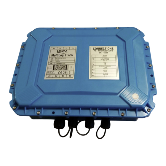
VERVIEW AND PREPARATION FOR USE 2.1 L OGGER EVICE VERVIEW The Multilog2WW logger family is flexible in design and can be built to suit a variety of uses. An example is shown opposite. Your logger may be different to the one illustrated; several models exist within the Multilog2WW family. -
Page 7: Preparing A Laptop Pc (Or Similar Device) For Use With Loggers
The logger devices require a user-interface in order to setup and test the unit. This is provided by means of a HWM software tool which is to be installed onto a Personal Computer (or similar device). The PC must have a USB port and Internet capability (for occasional use). - Page 8 If the logger has the feature enabled, it can also be set to occasionally save additional data into a “secondary recording” memory area, (e.g., data sampled at a higher frequency). Note: This is not available on all supplied units and must be arranged through your sales representative before placing an order;...
-
Page 9: Server Integration - Storing And Viewing Data
Measurement data is initially stored within the loggers, until the next call-in time. The data can then be uploaded to the server using an encrypted format. Typically, the server used to receive and store the data will be a HWM DataGate server, although other servers may be used in conjunction with HWM software. -
Page 10: Communicating With The Logger
Support website, or from the following webpage: https://www.hwmglobal.com/idt-support/ Note: The user has to be registered by HWM and have a password to gain access). Refer to the IDT User-guide for information on how to install and use the tool. 2.5.2 Connecting the comms cable A communications cable is required to connect the logger to a USB port of a PC. -
Page 11: Loading Logger Settings Into Idt
2.5.3 Loading Logger settings into IDT Click ‘Read Device’. A progress bar will show across the top of the page. When completed, an information box will appear stating ‘Device Read Success’. Click “OK” to clear the box. The IDT-PC program has now read a copy of the unit’s program (settings) into the “current program”... -
Page 12: Activating The Logger / Start Recording Of Logged Data
2.5.4 Activating the logger / Start recording of logged data When Multilog2WW is shipped from the factory it is put into a “Shipping Mode” (see section 9.3). This mode is designed to preserve its battery life whilst being shipped or in long term storage;... -
Page 13: Setup And Test Of The Logger / Using Idt
ETUP AND TEST OF THE OGGER USING The Multilog2WW logger is largely compliant with the general-purpose basic logger functionality described in the IDT User-Guide. Refer to the IDT guide for information regarding setup (or confirmation of setup) of Multilog2WW. e.g. Setup of logger to local time. -
Page 14: Interfaces And Sensors Supported
NTERFACES AND SENSORS SUPPORTED Note: Support for specific interfaces or functions vary and are dependent upon the model supplied. 4.1 P HYSICAL FEATURES DENTIFYING CONNECTOR FUNCTIONS Refer to section 2.1 for a description of the physical features of the logger, including the label that provides identification of interface positions. -
Page 15: Supported Interfaces
4.2 S UPPORTED NTERFACES (Supplied interfaces are dependent on model part-number) Pressure Inputs: Description 4-pin Connector External Pressure transducer (Options: Standard or High Temperature or High accuracy). 6-pin Connector (As above. Includes ground screen). Coupling Internal Pressure Transducer (Options: 20 bar, 30 bar). (direct) Digital Pulse Inputs: Example Use (Bi Flow) -
Page 16: Logger Channel Types And Data Interpretation
For most sensor interfaces, follow the general guidance within the IDT user-guide; the logger complies with the description and examples of setup provided therein. However, some HWM sensors require specialised setup screens or have their own user- guide which provides further guidance. -
Page 17: Sdi-12 Interface Support
4.5 SDI-12 I NTERFACE UPPORT The logger SDI-12 interface provides the ability to expand the logger by linking it to other equipment via this serial interface. The external equipment drives any sensor electronics; one or multiple sensors may be attached to it. SDI-12 is a protocol in which the logger can make a request for a sensor reading to the attached equipment. -
Page 18: Sonicsens3 (Ultrasound Distance / Depth Sensor) Support
It is possible to obtain additional information from the sensor equipment, should it be required. The dimensions of the water channel can be given to it and also the water depth within the channel; from these the unit can calculate the cross-sectional fluid area and average fluid speed. - Page 19 The interface will require setup require calibration factors and other setup for the channel regarding what the data actually represents. Refer to IDT user guide for details.
-
Page 20: Installation
NSTALLATION 5.1 S UMMARY OF INSTALLATION STEPS Check the logger is suitable for use and that you have the required sensor • attachments. Check all cables are of a suitable length. Connect an appropriate communications cable and begin communications with •... -
Page 21: Installing The Logger
Ensure details of the site of logger deployment are recorded. • (The administration for the server could be handled by office staff, or the installer could use the HWM Deployment app). 5.2 I NSTALLING THE LOGGER The logger must be mounted in a suitable location where the sensors attached to it can reach their intended installation points. -
Page 22: Verification Of The Configuration
5.3 I NSTALLING THE ANTENNA AND TESTING CELLULAR COMMUNICATIONS Only use HWM-provided antenna for use with your logger, to ensure the radio interface meets approvals requirements (safety, etc). An antenna with the appropriate connector should be selected and attached, tightening finger-tight only. - Page 23 HWM support webpage: https://www.hwmglobal.com/antennas-support/ Troubleshooting a Call Test failure There are a number of reasons why a Call test may fail. The following points should be checked before calling HWM support for assistance: - Possible Problem Solution Network Busy due to excessive Retry the test after a few minutes.
-
Page 24: Connecting Sensors And Other Devices
ETER ULSE CABLE If you are using an open-ended connection cable provided by HWM for connection to a meter interface or pulse unit, then simply connect it to the relevant socket on the data logger. (Note: It will be labelled according to the type of interface, such as Flow input connector on logger. -
Page 25: Pressure Sensors
It is important that a waterproof connector housing is used, such as the “Tuff-Splice” enclosure available from HWM. Final Connection Note that Long data connections should always be made using screened cable. The use of screened cable will ensure maximum rejection of interference from outside sources. -
Page 26: External Pressure Sensors
Connect the Plug to the External Pressure interface on the logger. Ensure you feel the ‘Click’ as the connector locks into place. External Pressure input on logger. (For illustration purposes only; Logger shown is not Multiolog2WW) Note: HWM pressure transducer will include a calibration details label. - Page 27 Add the details from the calibration label on the cable into the logger using IDT (Refer to the IDT user-guide).
-
Page 28: Viewing Your Data
IEWING YOUR DATA The logger usually calls into a server, where the data can be stored for the entire deployment period to a site. Site data is best viewed with the viewing tool (usually a website) linked to the server that is used as the data-store. -
Page 29: Maintenance, Service And Repair
Batteries are only replaceable by a HWM approved service centre or relevantly • trained technician. Contact your HWM representative for more details if required. Batteries can be returned to HWM for disposal. To arrange the return, complete the • on-line RMA form: https://www.hwmglobal.com/hwm-rma/... -
Page 30: Putting The Equipment Into Shipping Mode
9.3 P UTTING THE EQUIPMENT INTO HIPPING Before long term storage, moving an installed unit, or shipping for repair, the logger should be put into “Shipping mode”. Be sure to upload any unsent data before this operation. To put the logger into shipping mode: Read the current configuration of the logger using IDT. - Page 31 All images, text and designs are protected by international and UK copywrite law and remain the property of HWM-Water. It is against the law to copy or use any of the content from the HWM website or literature without the written consent of HWM-Water.
Need help?
Do you have a question about the Multilog 2 WW and is the answer not in the manual?
Questions and answers