Table of Contents
Advertisement
User Guide:
Warning:
This manual contains important safety and operating information.
Please read, understand, and follow the instructions in the manual
and also any safety / approvals documents shipped with the device.
LoLog 450, 500, Vista
- Installation and Setup
(using the IDT app)
1
MAN-110-0009-A January 2023.
Advertisement
Table of Contents

Subscribe to Our Youtube Channel
Related Manuals for HWM LoLog 450


Summary of Contents for HWM LoLog 450
- Page 1 User Guide: LoLog 450, 500, Vista - Installation and Setup (using the IDT app) Warning: This manual contains important safety and operating information. Please read, understand, and follow the instructions in the manual and also any safety / approvals documents shipped with the device.
-
Page 2: Table Of Contents
TABLE OF CONTENTS Introduction ........................4 Documentation and Support of Product ..............4 Operating Temperature .................... 4 Overview and preparation for use ................... 5 Physical Features & Interface Identification ............5 2.1.1 LoLog450 ......................5 2.1.2 LoLog 500 and LoLog Vista ................6 Communications Links (for programming and data download) ...... - Page 3 Retrieving, storing, and viewing data................20 Viewing your data on the server ................20 6.1.1 Identifying your logger’s data (using site or SMS number) ......21 Troubleshooting ......................21 Maintenance, Service and Repair................... 22 Cleaning ........................22 Replaceable parts ....................22 Return of product for Service or Repair ..............
-
Page 4: Introduction
NTRODUCTION Thank you for choosing a HWM device. We trust it will provide you with many years of service. The “LoLog” family consists of LoLog 450, LoLog 500 and LoLog Vista devices. Each logger can be built and configured to suit specific applications; several models of each type are available. -
Page 5: Overview And Preparation For Use
On the LoLog 500 and LoLog Vista models, they are positioned on the rear and side faces of the unit. On the LoLog 450 they are positioned on the rear face. The label (see Figure 1) will indicate the LoLog model name (e.g., LoLog 500) and the part-number of the unit, the latter... -
Page 6: Lolog 500 And Lolog Vista
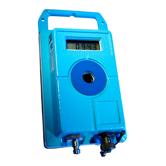
In the centre of the logger there is a window (surrounded by a magnetic ring) which is used for Infrared communications. An infrared communications cable (refer to section2.2), available from HWM, is required for communications with the logger. The magnetic ring holds the communications interface in position during use. -
Page 7: Communications Links (For Programming And Data Download)
OMMUNICATIONS INKS FOR PROGRAMMING AND DATA DOWNLOAD To communicate with the logger, an infrared communications interface is required. E.g., HWM part-number “RAG R10USB”. The interface is known as the “USB IR Reader” (See Figure 6 and Figure 7). Figure 7. -
Page 8: Idt - Used With A Tablet Device (Via Usb)
The LoLog devices require a user-interface in order to setup and test the unit. This is provided by a HWM software tool / app called “IDT” (“Installation and Diagnostic Tool”). This must be installed on a tablet or mobile phone device. Refer to the IDT app user- guide for further information and installation instructions. -
Page 9: Logger Activation Process (For First-Time Use)
used to produce “average” values. Where a logger has an unused interface, the related channel can be disabled to reduce battery power consumption and the saving of zero/null or erroneous data. The LoLog series loggers have the options of analogue inputs or digital inputs (usually used for meter pulse detection), or one of each. -
Page 10: Interfaces And Sensors
Some loggers have a connector for attaching or removing a sensor, whilst others may include the sensor permanently attached (e.g., a pulse detection head). Sensors provided by HWM will include a cable with a suitable connector for the logger. 3.2 P... -
Page 11: Available Pressure Ranges
LoLog loggers are supplied factory-calibrated for use with the supplied pressure trandsucer. It is not possible for the user to re-calibrate the unit. If re-calibration is required, discuss the avaibility of the service with your HWM representative. 3.2.5 Re-zero facility (for pressure relative to local atmosphere) The sensors normally measure pressure relative to atmospheric pressure. -
Page 12: Flow Sensor Input (Meter Pulse Collection)
3.3 F ENSOR NPUT METER PULSE COLLECTION Depending on the model supplied, the logger may have 0, 1 or 2 Flow inputs. These are digital inputs, designed to sense the open or closed condition of a switch (activated by the installed meter). To use the flow channel(s) the logger must be set up (using IDT) to know what each meter pulse represents. -
Page 13: Via A Glanded Cable With 4-Pin Connector
Various types of pulse-head are available. When ordering the logger, ensure the pulse- head fitted is the one you require, (i.e., that it will be suitable for use with the meter). (Discuss with your HWM representative prior to ordering). 3.4 4-20... -
Page 14: Pinout / Installation Cables
FLOW / DIRECTION Maximum frequency 64Hz Minimum pulse width 8mS Figure 19. Schematic (typical digital flow input circuit) LoLog 4 Pin MIL-spec Connector (Flow) Title Description Typical HWM cable colours (for Flow) Not connected Flow Flow input signal (pulses) Blue GND (0V) -
Page 15: Milliamp Input (4-20Ma)
Logger input 4-20mA ciruit transmitter Figure 20. Schematic (typical milliamp input circuit) LoLog 4 Pin MIL-spec Connector (milliamp) Title Description Typical HWM cable colours (for milliamp) +VE signal Positive mA input signal Blue -VE signal Negative mA input signal Yellow... -
Page 16: Installation Steps
Check that the logger is in a “recording” state. For use of the logger with the DataGate system, ensure details of the site of logger • deployment are recorded. (Use of the HWM Deployment app is recommended to reduce the server administration required by office staff). -
Page 17: Using The Idt App
SING THE Refer to the IDT app user-guide for guidance regarding use of IDT. The IDT guide covers several logger models, including setup of most of the functionality for the LoLog series. It can also be used to test sensor are operating correctly. The IDT app must have a communications path to the logger;... - Page 18 Note: The LoLog 450 and LoLog 500 also have this option within IDT. These can be set to “off” since no display exists on these models. Any other setting is irrelevant. To setup the display of a specific channel, tap on the “Mode” line of that channel.
-
Page 19: Memory Management
Results for a digital channel (such as meter pulses indicating Flow) are preceded by a code of 3 digits, then ‘F’. When displaying a total (e.g., for a flow channel), the number is 12 digits in length, and thus is too big to display within the 4 LCD digits. The value is therefore displayed by spreading it over 3 sets of 4-digits. -
Page 20: Check Of Status Before Leaving Site
When logged into the IDT app, logger data can be transferred to the server for storage. The data is then best viewed with the viewing portal (website) recommended by your HWM representative (e.g., DataView, shown below). Figure 27. Example of data seen using an on-line data viewing tool DataGate can also (by arrangement with your sales representative) be used to export logger data to other servers. -
Page 21: Identifying Your Logger's Data (Using Site Or Sms Number)
DataGate server (e.g., by use of the HWM Deployment app). To find the logged data on the web-page normally requires a search for the name or address of the site. -
Page 22: Maintenance, Service And Repair
If returning to HWM, this can be done by completing the on-line RMA form: https://www.hwmglobal.com/hwm-rma/ Prior to shipping, put the equipment into a ‘stopped’ state (refer to the IDT app user- guide for instructions). - Page 23 All images, text and designs are protected by international and UK copywrite law and remain the property of HWM-Water. It is against the law to copy or use any of the content from the HWM website or literature without the written consent of HWM-Water.
Need help?
Do you have a question about the LoLog 450 and is the answer not in the manual?
Questions and answers