Table of Contents
Advertisement
REPAIR
Important Safety Instructions
Read all warnings and instructions in this
manual. Save these instructions.
- For portable spray applications of architectural paints and coatings -
190ESt
Airless Paint Sprayers
3000 psi (207 bar, 20.7 MPa ) Maximum Working Pressure
120 VAC
232900, A, B, C, D, E, F
232901, A, B, C, D, E
233797, A, B, C, D, E
233815, A, B, C, D, E
100- - 120 VAC
232903, A, B
220- - 240 VAC
232906, A, B
Component Function and Identification
. . . . . . . . . . . . . . . . . . . . . . . . . . . . . . . . . . . . .
. . . . . . . . . . . . . . . . . . . . . . . . . . . . . . . .
. . . . . . . . . . . . . . . . . . . . . . . . . . . . . . . . . . . . .
Table of Contents
. . . . . . . . . . . .
. . . . . . . . . . . . . . . . . . . . . . .
. . . . . . . . . . . . . . . . . . . . . .
. . . . . . . . . . . . . . . . . . . . .
. . . . . . . . . . . . . . . . . . . .
First choice when
quality counts.t
ti7400a
. . . . . . .
309365
. . . . . . .
309045
. . . . . . . . . . . . . . . . . . . . .
. . . . . . .
309065
5
6
7
8
9
. . . . . . . . . . . . . . . . . . . . . . . . . . . . . . . .
12
Graco Phone Number
12
14
Graco Warranty
309063F
232900
. . . . . . .
309064
. . . . . . . . . . . . . . . . . . . . . . .
. . . . . . . . . . . . . . . . . . . .
. . . . . . . . . . . . . . . . . . . . . . . . . . . .
. . . . . . . . . . . . . . .
. . . . . . . . . . . . . . . . . . . . . . . . . .
. . . . . . . . . . . . . . . . . . . . . . . . . . . . . . .
309060
19
24
25
26
27
28
28
Advertisement
Table of Contents

Related Manuals for Graco 190ES 309063F


Summary of Contents for Graco 190ES 309063F
-
Page 1: Table Of Contents
Table of Contents ... . Pressure Control Repair Drive Housing Replacement Motor Replacement Displacement Pump Replacement Technical Data Graco Phone Number Graco Warranty First choice when quality counts.t ti7400a 232900 309365 . -
Page 2: Specifications
This equipment is not intended for use with flammable or combustible materials used in places such as cabinet shops or other “factory” or fixed locations. If you intend to use this equipment in this type of application, you must comply with NFPA 33 and OSHA requirements for the use of flammable and combustible materials. -
Page 3: Fire And Explosion Hazard
The following are general Warnings related to the safe setup, use, maintenance and repair of this equipment. Additional, more specific warnings may be found throughout the text of this manual where applicable. FIRE AND EXPLOSION HAZARD Flammable fumes, such as solvent and paint fumes, in work area can ignite or explode. To help prevent fire and explosion: D Use equipment only in well ventilated area. - Page 4 D Check equipment daily. Repair or replace worn or damaged parts immediately. D Do not alter or modify equipment. D Use equipment only for its intended purpose. Call your Graco distributor for information. D Route hoses and cables away from traffic areas, sharp edges, moving parts and hot surfaces.
-
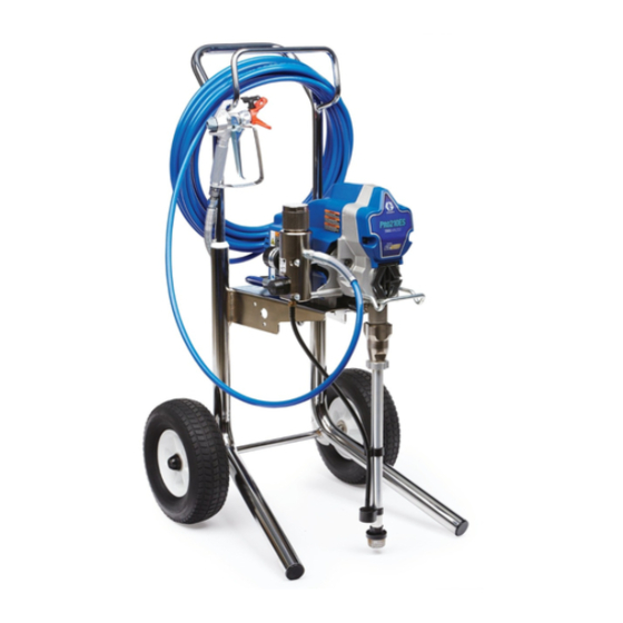
Page 5: Component Identification And Function
Component Identification and Function Motor Drive Assembly Displacement Pump Fluid Outlet Prime Valve Fluid Filter (optional) Pressure Adjusting Knob Pressure Control ON/OFF Switch 50 ft (15 m) Main Hose Spray Gun RAC IV Switch Tip Tip Guard Thumb Lock Safety Power Cord Rack Suction Hose Drain Tube... -
Page 6: Pressure Relief Procedure
Pressure Relief Procedure WARNING SKIN INJECTION HAZARD Follow this Pressure Relief Procedure whenever you are instructed to relieve pressure, stop spraying, check or ser- vice equipment, or install or clean spray tip. read Injection Hazard Warning. 1. Turn OFF power and turn pressure control to low- est pressure setting. -
Page 7: General Repair Information
General Repair Information WARNING Read Electric Shock Warning and Burn Hazard Warning. WARNING Flammable materials spilled on hot, bare, motor could cause fire or explosion. To reduce risk of burns, fire or explosion, do not operate sprayer with cover removed. D Keep all screws, nuts, washers, gaskets, and electrical fittings removed during repair procedures. -
Page 8: Grounding And Electric Requirements
Grounding and Electric Requirements WARNING Your system must be grounded. Read warnings, page 3. The sprayer cord includes: a grounding wire with an appropriate grounding contact. Fig. 3 The sprayer requires: 110--120V units: 100--130 VAC, 50/60 Hz, 15A, 1 phase, circuit with a grounding receptacle. 240V Units: 210--255 VAC, 50/60 Hz, 7.5A, 1 phase, circuit with a grounding receptacle. -
Page 9: Motor Won't Operate
Relieve pressure; page 6. MOTOR WON’T OPERATE TYPE OF PROBLEM WHAT TO CHECK If check is OK, go to next check 1. Pressure control knob setting. Motor will not run Basic Fluid Pressure if at minimum setting (fully counterclockwise). Problems 2. -
Page 10: Low Or Fluctuating Output
LOW OR FLUCTUATING OUTPUT TYPE OF PROBLEM WHAT TO CHECK If check is OK, go to next check Low Output 1. For worn spray tip. 2. Verify pump does not continue to stroke when gun trigger is released. 3. Filter clogged (If optional filter is installed). 4. - Page 11 LOW OR FLUCTUATING OUTPUT TYPE OF PROBLEM WHAT TO CHECK If check is OK, go to next check Motor runs and pump strokes 1. Paint supply. 2. Intake strainer clogged. 3. Suction tube or fittings loose. 4. To see if intake valve ball and piston ball are seating properly.
-
Page 12: Spin Test
Setup Electric Shock Hazard; page 6. To check armature, motor winding and brush electrical continuity: Relieve pressure; page 6. 2. Remove drive housing; page 24. 3. Fig. 7. Remove pressure control cover (39). Dis- connect red and black motor leads from control board. - Page 13 Motor Brush Replacement 6. Fig. 9. Insert brush (B). Push cap (A) into place over brush. Orient each cap with the 2 projections on either side of the brush lead. You will hear a “snap” when cap is securely in place. CAUTION When installing brushes, follow all steps carefully to avoid damaging parts.
-
Page 14: On/Off Switch Replacement
On/Off Switch Replacement 120 Vac Removal Relieve pressure; page 6. 2. Fig. 10 and 11. Remove four screws (18) and pressure control cover (39). 3. Disconnect two wires (A) from ON/OFF switch (23). 4. Remove toggle boot (25) and locking ring (24). Remove ON/OFF switch (23). -
Page 15: Wiring Diagram
On/Off Switch Replacement 120 Vac ON/OFF Switch Power Plug Black White Green from Motor Black (--) ON/OFF Switch White Black Power Green Plug Red (+) Black (--) from Motor Fig. 11 L2 L1 Yellow Red (+) Capacitor Capacitor M- - Yellow Wiring Diagram (Capacitor on Motor) - Page 16 Black ON/OFF Switch Green Power Cord Motor Connector ti7415a Fig. 309063 Wiring Diagram (Capacitor on PC board) Black White White 232900, F, 232901, E 233797, E 233815, E Pressure Switch Black...
- Page 17 On/Off Switch Replacement 100 Vac (232903) Removal Relieve pressure; page 6. 2. Fig. 13. Remove four screws (18) and pressure control cover (39). 3. Disconnect four wires (A) from ON/OFF switch (23). 4. Remove toggle boot (25) and locking ring (24). Remove ON/OFF switch (23).
- Page 18 On/Off Switch Replacement 240 Vac (232906) Removal Relieve pressure; page 6. 2. Fig. 14. Remove pressure control cover (39). 3. Disconnect four wires (A) at ON/OFF switch (23). 4. Remove toggle boot (25) and locking ring (24). Remove ON/OFF switch (23). Caution Heat from inductor coil of filter board may destroy wire insulation that...
-
Page 19: Pressure Control Repair
Pressure Control Repair For these models and series only: 232900 A, B, C, D, E 232901 A, B, C, D 233797 A, B, C, D 233815 A, B, C, D 232903 A, B 232906 A, B Note: Keep a new transducer on hand to use for test. CAUTION Do not allow sprayer to develop fluid pressure with- out transducer installed. -
Page 20: Motor Control Board
Pressure Control Repair For these models and series only: 232900 A, B, C, D, E 232901 A, B, C, D 233797 A, B, C, D 233815 A, B, C, D 232903 A, B 232906 A, B Removal Refer to Fig. 10 and 11, 13 or 14 depending on sprayer voltage. -
Page 21: Pressure Adjust Potentiometer
Pressure Control Repair For these models and series only: 232900 A, B, C, D, E 232901 A, B, C, D 233797 A, B, C, D 233815 A, B, C, D 232903 A, B 232906 A, B Pressure Control Transducer Removal Refer to Fig. - Page 22 Pressure Control Repair For these models and series only: 232900 F 232901 E 233797 E 233815 E Motor Control Board Removal Relieve pressure; page 6. 2. Remove 4 screws (17) and control cover (16). 3. Disconnect motor connector, pressure control connector white wire to control board (8) and black wire to switch (4).
-
Page 23: Pressure Control
Pressure Control Repair For these models and series only: 232900 F 232901 E 233797 E 233815 E Pressure Control Removal (See Fig. 15) Relieve pressure; page 6. 2. Remove 4 screws (17) and control cover (16). 3. Disconnect pressure control connector from con- trol board (8). -
Page 24: Drive Housing Replacement
Drive Housing Replacement CAUTION Do not drop gear cluster (7) when removing drive housing (10). Gear cluster may stay engaged in motor front end bell or drive housing. Disassembly Relieve pressure; page 6. 2. Remove pump (13); Displacement Pump Re- placement, page 26. -
Page 25: Motor Replacement
Motor Replacement Disassembly Relieve pressure; page 6. 2. Remove pump; Displacement Pump Replace- ment, page 26. CAUTION Do not drop gear cluster (7) when removing drive housing (10). Gear cluster may stay engaged in motor front end bell or drive housing. 3. -
Page 26: Displacement Pump Replacement
Tighten jam nut by hand, then tap 1/8 to 1/4 turn with a 20 oz (maximum) hammer to approxi- mately 75 +/--5 ft-lb (102 N¡m). Fig. 21 ti5916a 7. Fig. 22. Fill packing nut with Graco TSL until fluid flows onto top of seal. TI0062 Fig. 22 ti5916a 8. -
Page 27: Technical Data
100--120V, ∅, 220--240V, ∅, Generator A, Hz A, Hz Minimum W 1, 15, 50/60 1, 10, 50/60 3000 Basic Sprayer Wetted Parts: ......zinc-plated carbon steel, polyurethane, polyethylene, stainless steel, PTFE, Delrin er, V-Maxt UHMWPE, aluminum, stainless steel,... -
Page 28: Graco Information
Graco Information TO PLACE AN ORDER OR FOR SERVICE, contact your Graco distributor, or call 1- -888- -541- -9788 to identify the nearest distributor. All written and visual data contained in this document reflects the latest product information available at the time of publication.
Need help?
Do you have a question about the 190ES 309063F and is the answer not in the manual?
Questions and answers