Viking VCBB536 Service Manual
Built-in bottom-mount refrigerator/freezer
Hide thumbs
Also See for VCBB536:
- Specifications (153 pages) ,
- Product brochure (56 pages) ,
- Specification sheet (10 pages)
Table of Contents
Advertisement
Quick Links
Service
Manual
This manual is to be used by qualified appliance technicians only.
Viking does not assume any responsibility for property damage
or personal injury for improper service procedures done by an
unqualified person.
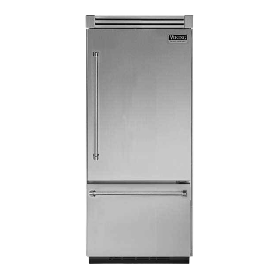
Built-In
Bottom-Mount
Refrigerator/
Freezer
Preferred Service
This Base Manual covers general and
specific information including, but not
limited to the following models:
VCBB536
VIBB536
DDBB536
DFBB536
SMR-0007
August 1, 2009
Advertisement
Table of Contents


Need help?
Do you have a question about the VCBB536 and is the answer not in the manual?
Questions and answers