
Related Manuals for Rigol DG1012


Summary of Contents for Rigol DG1012
- Page 1 User’s Guide RIGOL Publication Number UGB06109-1210 Nov. 2008 Dual-Channel Function/Arbitrary Waveform Generator DG1022, DG1012 © 2008 RIGOL Technologies, Inc. All Rights Reserved...
- Page 3 Information in this publication replaces all previous corresponding material. RIGOL reserves the right to modify or change part of or all the specifications and pricing policies at company’s sole decision. NOTE: RIGOL is registered trademark of RIGOL Technologies, Inc.
- Page 4 Avoid Circuit or Wire exposed. Do not touch the exposed connections or components when the power is turn-on. Do not operate with suspected failures. If you suspect there is damage with this product, have it inspected by qualified service personnel authorized by RIGOL before further operations. Provide Proper Ventilation.
- Page 5 Symbols on the Product. These symbols may appear on the Instrument: Hazardous Refer to the Protective Grounding Test Voltage Instructions earth terminal Terminal Grounding of Chassis Terminal © 2008 RIGOL Technologies, Inc. User’s Guide for DG10× 2 Series...
-
Page 6: Instrument At A Glance
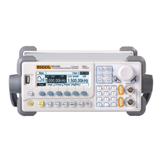
Function/Arbitrary Waveform Generators: DG1022、DG1012 RIGOL DG10× 2 Series Dual-Channel Function/ Arbitrary Waveform Generator adopt the DDS technology, which can provide stable, high-precision, pure and low distortion sine signal. It can also provide 5MHz square waveform with fast rising and falling edges. - Page 7 NOTE: All the descriptions in this guide are according to DG1022, if you need to know the Chapter 5 Specifications particular specifications about DG1012, please look over “ ”. © 2008 RIGOL Technologies, Inc. User’s Guide for DG10× 2 Series...
-
Page 8: Table Of Contents
To Set the Utility Function ................ 2-49 To Set the Sync Output ..............2-52 Basic Setting of the Two Channels ............2-54 Channel Coupling Settings ..............2-57 To Set the Counter ................2-59 © 2008 RIGOL Technologies, Inc. User’s Guide for DG10× 2 Series... - Page 9 Chapter 6 Appendix ................6-1 Appendix A: Accessories ................6-1 Appendix B: Warranty ................6-2 Appendix C: General Care and Cleaning ............6-3 Appendix D: Contact RIGOL ..............6-4 © 2008 RIGOL Technologies, Inc. User’s Guide for DG10× 2 Series...
-
Page 11: Chapter 1 Quick Start
The Front/Rear Panel 1-4 User Interface 1-6 To Set a Waveform 1-7 To Set the Output 1-11 To Set Modulation/Sweep/Burst 1-12 To Use Digital Input 1-14 To Use Store/Utility/Help Function 1-15 © 2008 RIGOL Technologies, Inc. User’s Guide for DG10× 2 Series... -
Page 12: General Inspection
RIGOL Sales Representative. If the shipping container is damaged, or the cushioning materials show signs of stress, notify the carrier of your RIGOL sales office. Keep the shipping materials for the carrier’s inspection. RIGOL offices will arrange for repair or replacement at RIGOL’s option without waiting for claim settlement. -
Page 13: Handle Adjustment
Then, make the handle rotate to the desired position. The operating methods are shown below in Figure 1-1 and Figure 1-2. Figure 1-1 Handle Adjusting Figure 1-2 Adjustable Positions © 2008 RIGOL Technologies, Inc. User’s Guide for DG10× 2 Series... -
Page 14: The Front/Rear Panel
Channel Keypad CH2 Output CH2 Output/ Switch Keys Switch Button Counter Input Power Menu Keys CH1 Output CH1 Output Button Connector Figure 1-3 Front Panel for DG10× 2 Series © 2008 RIGOL Technologies, Inc. User’s Guide for DG10× 2 Series... - Page 15 The Rear Panel at a Glance 10MHz Synchronous Reference Input Output Power Socket Modulation External USB Device Main Power Input Trig/FSK/Burst Switch Figure 1-4 Rear Panel for DG10× 2 Series © 2008 RIGOL Technologies, Inc. User’s Guide for DG10× 2 Series...
-
Page 16: User Interface
Sine which represents the functional key with “Sine” on it on the front panel, while the menu buttons are represented by shadow words such as Freq, which means the “Frequency” option in the Sine menu. © 2008 RIGOL Technologies, Inc. User’s Guide for DG10× 2 Series... -
Page 17: To Set A Waveform
Square signal with frequency from 1μHz to 5MHz and Frequency/Period, Amplitude/ High Level, Offset/ variable duty cycle. By setting Low level, Duty Cycle and Phase , Square signal with different parameters can be © 2008 RIGOL Technologies, Inc. User’s Guide for DG10× 2 Series... - Page 18 Pulse Width. By setting Low level, Pulse Width/Duty Cycle and Delay , Pulse signal with different parameters can be generated. Figure 1-12 Pulse Signal in the Menu Display Mode © 2008 RIGOL Technologies, Inc. User’s Guide for DG10× 2 Series...
- Page 19 Arbitrary waveform Signal in the Menu Display Mode As shown in Figure 1-14, the default Exponential Rise Signal parameters are: 1kHz Frequency, 5.0 V Amplitude, 0 V Offset and 0° initial phase. © 2008 RIGOL Technologies, Inc. User’s Guide for DG10× 2 Series...
- Page 20 Graph Mode in single channel and Menu Mode in double channel. If the instrument is in remote mode, press this button it will return to local mode. 1-10 © 2008 RIGOL Technologies, Inc. User’s Guide for DG10× 2 Series...
-
Page 21: To Set The Output
In the Counter mode, the output connector of CH2 is used as the signal input terminal. At the same time, the output of CH2 will be disabled automatically. © 2008 RIGOL Technologies, Inc. 1-11 User’s Guide for DG10× 2 Series... -
Page 22: To Set Modulate/Sweep/Burst
2. Press the Sweep button, Sine, Square, Ramp or Arbitrary waveform can be swept (Pulse, Noise and DC can not be swept). In the Sweep Mode, DG10× 2 Series generate signal with variable frequencies. 1-12 © 2008 RIGOL Technologies, Inc. User’s Guide for DG10× 2 Series... - Page 23 Burst can last for certain times of waveform cycle (N-Cycle Burst) or be controlled by external gated signals (Gated Burst). Burst applies to all kinds of waveforms, but noise can only be used in gated burst. © 2008 RIGOL Technologies, Inc. 1-13 User’s Guide for DG10× 2 Series...
-
Page 24: To Use Digital Input
1. Use the Direction keys to move the cursor left or right. Rotate the knob to change a digit (clockwise to increase). 2. Use the Keypad to set the parameters values of the waveforms, which can change its value directly. 1-14 © 2008 RIGOL Technologies, Inc. User’s Guide for DG10× 2 Series... -
Page 25: To Use Store/Utility/Help Function
3. The Help Button is used to read the help information. Operation Instruction To get help: Press the key and last 2~3 second, then the help message will appear. © 2008 RIGOL Technologies, Inc. 1-15 User’s Guide for DG10× 2 Series... -
Page 27: Chapter 2 Operating Your Generator
Basic Setting of the Two Channels 2-54 Channel Coupling Settings 2-57 To Set the Counter 2-59 System Settings 2-63 I/O Settings 2-70 Test/Cal Settings 2-71 To Use the Help System 2-73 © 2008 RIGOL Technologies, Inc. User’s Guide for DG10× 2 Series... -
Page 28: To Set Basic Waveforms
Setting the initial phase of the signal NOTE: Waveforms in single channel needn’t to set the Aligpha parameter. It is always used to align the phases of the two channels’ output signals. © 2008 RIGOL Technologies, Inc. User’s Guide for DG10× 2 Series... - Page 29 When using the knob to input, use the direction buttons to select the digit you want to edit and rotate the knob to change its value. © 2008 RIGOL Technologies, Inc. User’s Guide for DG10× 2 Series...
- Page 30 Use the keypad or the knob to input the desired value, choose the unit, and press the corresponding button. Current Parameter: Amplitude Figure 2-3 Setting the Amplitude NOTE: The “dBm” option will appear only when the output impedance is set to “50”. © 2008 RIGOL Technologies, Inc. User’s Guide for DG10× 2 Series...
- Page 31 Current Parameter: Offset Figure 2-4 Setting the Offset NOTE: The setting of any waveform for Offset is the same as sine wave, so we will not cover this topic again. © 2008 RIGOL Technologies, Inc. User’s Guide for DG10× 2 Series...
- Page 32 Setting the initial phase After finishing the above operations, press View , in the Graph Mode, the waveform is shown in the following figure. Figure 2-6 Waveform Parameter in the Graph Mode © 2008 RIGOL Technologies, Inc. User’s Guide for DG10× 2 Series...
-
Page 33: To Set Square Waveform
Setting the signal’s Offset or Low Level; the Level current parameter will switch at a second press Duty Cycle Setting the Duty Cycle for Square Waveform Phase Setting the initial phase of the signal © 2008 RIGOL Technologies, Inc. User’s Guide for DG10× 2 Series... - Page 34 Duty Cycle: The percentage that the High Level takes up in the whole Period. Please Note : for the Frequency Duty Cycle Value Below 3MHz(included): 20% to 80% From 3MHz to 4MHz (included): 40% to 60% From 4MHz to 5MHz (included): © 2008 RIGOL Technologies, Inc. User’s Guide for DG10× 2 Series...
- Page 35 Duty Cycle Figure 2-8 Setting the Duty Cycle Press View, in the Graph Mode, the waveform is shown in the following figure. Figure 2-9 Waveform Parameters in the Graph Mode © 2008 RIGOL Technologies, Inc. User’s Guide for DG10× 2 Series...
-
Page 36: To Set Ramp Waveform
Setting the Symmetry for Ramp Waveform Phase Setting the initial phase of the signal Term Explanation: Symmetry: The percentage that the Rising Period takes up in the whole Period. Input Range: 0~100% 2-10 © 2008 RIGOL Technologies, Inc. User’s Guide for DG10× 2 Series... - Page 37 Symmetry Figure 2-11 Setting the Symmetry Press View, in the Graph Mode, the waveform is shown in the following figure. Figure 2-12 Waveform Parameter in the Graph Mode © 2008 RIGOL Technologies, Inc. 2-11 User’s Guide for DG10× 2 Series...
-
Page 38: To Set Pulse Waveform
Setting the Delay time. Term Explanation: Pulse Width: The time span between thresholds of 50% of the rising edge amplitude to the next 50% of the falling edge amplitude. 2-12 © 2008 RIGOL Technologies, Inc. User’s Guide for DG10× 2 Series... - Page 39 1ms, the pulse width is 500µs and the duty cycle is 50%, when setting the pulse width to be 200µs, the duty cycle will become 20%. © 2008 RIGOL Technologies, Inc. 2-13 User’s Guide for DG10× 2 Series...
- Page 40 Figure 2-15 Setting the Delay time Press View, in the Graph Mode, the waveform is shown as in the following figure. Figure 2-16 Waveform parameters in the Graph mode 2-14 © 2008 RIGOL Technologies, Inc. User’s Guide for DG10× 2 Series...
-
Page 41: To Set Noise Waveform
Press View, in the Graph Mode, the waveform is shown in the following figure. Figure 2-18 Waveform Parameter in the Graph Mode © 2008 RIGOL Technologies, Inc. 2-15 User’s Guide for DG10× 2 Series... -
Page 42: To Set Arbitrary Waveforms
Load Select the built-in Arbitrary Signal as Output. Edit Create and Edit Arbitrary Waveform. Phase Setting the initial phase of the signal 2-16 © 2008 RIGOL Technologies, Inc. User’s Guide for DG10× 2 Series... -
Page 43: To Select Arbitrary Waveform
When there is no waveform stored in the Non-Volatile Memory, the Stored Menu and the Delete Menu will hide. When there is no waveform in the Volatile Memory, the Volatile menu will hide. © 2008 RIGOL Technologies, Inc. 2-17 User’s Guide for DG10× 2 Series... - Page 44 As shown in the following figure, Press Math, use the knob to choose “ExpRise” and press Select. Press View to view the waveform of “ExpRise” function. Figure 2-22 Choose “ExpRise” function 2-18 © 2008 RIGOL Technologies, Inc. User’s Guide for DG10× 2 Series...
- Page 45 RIGOL Figure 2-23 Waveform Parameter in the Graph Mode © 2008 RIGOL Technologies, Inc. 2-19 User’s Guide for DG10× 2 Series...
- Page 46 Recall information in the specific position in the memory. Save the waveform to the appointed Store place Remove any waveform that has been Remove stored in the memory 2-20 © 2008 RIGOL Technologies, Inc. User’s Guide for DG10× 2 Series...
-
Page 47: To Edit Arbitrary Waveform
When there is no waveform stored in the Non-Volatile Memory, the Stored Menu and the Delete Menu will hide. When there is no waveform in the Volatile Memory, the Volatile menu will hide. © 2008 RIGOL Technologies, Inc. 2-21 User’s Guide for DG10× 2 Series... - Page 48 Activate the linear Interpolation between the Interp On/ defined points Deactivate the linear Interpolation between the defined points Set the number of points when Initializing Points the waveform EditPt Start the Waveform Editor 2-22 © 2008 RIGOL Technologies, Inc. User’s Guide for DG10× 2 Series...
- Page 49 Press Arb Edit Create EditPt, The waveform can be defined by setting the time and voltage for each point using this function. The interface is as follows: Figure 2-28 Operation Menu © 2008 RIGOL Technologies, Inc. 2-23 User’s Guide for DG10× 2 Series...
- Page 50 Remove Save the created waveform to the Save non-Volatile Memory. Instruction: The time for the last definable point should be less than the cycle period in the waveform. 2-24 © 2008 RIGOL Technologies, Inc. User’s Guide for DG10× 2 Series...
- Page 51 After the storage, press Recall to read the waveform to volatile memory. Press View, the edited waveform is shown in the following figure. Default Arbitrary Waveform Figure 2-32 Waveform under the Graph Mode © 2008 RIGOL Technologies, Inc. 2-25 User’s Guide for DG10× 2 Series...
- Page 52 Recall to recall and edit it in the Volatile memory. As shown in the following figures, users can edit the parameters as in need and store it after the modification. Figure 2-34 Edit the waveform parameters 2-26 © 2008 RIGOL Technologies, Inc. User’s Guide for DG10× 2 Series...
-
Page 53: To Set Modulated Waveforms
In PM, users can set the Source (Internal/ External), Phase Deviation, Modulating Frequency, Modulating Waveform and Carrier Waveform, etc. We will introduce how to set these parameters in details according to different types of modulation. © 2008 RIGOL Technologies, Inc. 2-27 User’s Guide for DG10× 2 Series... -
Page 54: To Set Am Waveform
Choose internal modulating Waveform: Sine SrcInt Square Triangle Shape UpRamp DnRamp Noise Choose External modulation, the modulating SrcExt waveform is inputted form the [Modulation In] port on the rear panel. 2-28 © 2008 RIGOL Technologies, Inc. User’s Guide for DG10× 2 Series... - Page 55 For an external source, the depth of AM is controlled by the voltage level of the connector connected to the [Modulation In]. +5V external source corresponds to the 100% internal Modulation. © 2008 RIGOL Technologies, Inc. 2-29 User’s Guide for DG10× 2 Series...
-
Page 56: To Set Fm Waveform
UpRamp DnRamp Noise Choose External modulation, the modulating waveform is inputted form the [Modulation In] SrcExt Deviat. port on the rear panel. Only “Deviat.” needs to be set. 2-30 © 2008 RIGOL Technologies, Inc. User’s Guide for DG10× 2 Series... - Page 57 Connector connected to the [Modulation In]. +5V corresponds to the selected Deviation. Lower external voltage generates less deviation, while negative voltage reduces the modulated signal frequency to below the corresponding carrier’s. © 2008 RIGOL Technologies, Inc. 2-31 User’s Guide for DG10× 2 Series...
-
Page 58: To Set Fsk Waveform
Carrier Waveform used in FSK can be set through the Sine、 Square、 Ramp、 Arb button on the front panel. Press Mod Type FSK, enter the following interface. Figure 2-39 FSK Waveform Parameter Setting Interface 2-32 © 2008 RIGOL Technologies, Inc. User’s Guide for DG10× 2 Series... - Page 59 Only “HopFreq” needs to be set. Press View, in the Graph Mode, the waveform is shown in the following figure. FSK Frequency Hop Frequency Figure 2-40 Waveform Parameter in the Graph Mode © 2008 RIGOL Technologies, Inc. 2-33 User’s Guide for DG10× 2 Series...
-
Page 60: To Set Pm Waveform
Deviat. [Modulation In] port on the rear panel. Only “Deviat.” needs to be set. Press View, in the Graph Mode, the waveform is shown in the following figure. 2-34 © 2008 RIGOL Technologies, Inc. User’s Guide for DG10× 2 Series... - Page 61 RIGOL Modulating Frequency Phase Deviation Figure 2-42 Waveform Parameter in the Graph Mode © 2008 RIGOL Technologies, Inc. 2-35 User’s Guide for DG10× 2 Series...
-
Page 62: To Generate Sweep Signal
Manual: Choose manual trigger. Press Manual will trigger a Sweep. Trigger : Signal Triggered at Rise Edge TrigOut : Signal Triggered at Fall Edge Off: Turn off Trigger Setting Finish Setting 2-36 © 2008 RIGOL Technologies, Inc. User’s Guide for DG10× 2 Series... - Page 63 To Sweep upward, set the Start Frequency lower than the Stop Frequency, or set a positive frequency interval. To Sweep downward, set the Start Frequency higher than the Stop Frequency, or set a negative frequency interval. © 2008 RIGOL Technologies, Inc. 2-37 User’s Guide for DG10× 2 Series...
-
Page 64: To Generate Burst Signal
Press the Burst button, in the Normal Mode, the operation menu will appear on the screen, see Figure 2-59. Set the Waveform parameters by using the operation menu. Figure 2-44 Burst Waveform Parameter Setting Interface 2-38 © 2008 RIGOL Technologies, Inc. User’s Guide for DG10× 2 Series... - Page 65 Manual: Choose manual trigger. Press Manual will output a burst signal Trigger : Signal Triggered at Rise Edge TrigOut : Signal Triggered at Fall Edge Off: Turn off Trigger Setting Finish Setting © 2008 RIGOL Technologies, Inc. 2-39 User’s Guide for DG10× 2 Series...
- Page 66 Press View, in the Graph Mode, the waveform is shown in the following figure. Burst Period Start Phase Delay Cycle Times N-Cycle Figure 2-46 Waveform Parameter in the Graph Mode 2-40 © 2008 RIGOL Technologies, Inc. User’s Guide for DG10× 2 Series...
- Page 67 Set the Start Phase for the Gated Signal Press View, in the Graph Mode, the waveform is shown in Figure 2-63. Start Phase Positive Gated Signal Gated Figure 2-48 Waveform Parameter in the Graph Mode © 2008 RIGOL Technologies, Inc. 2-41 User’s Guide for DG10× 2 Series...
-
Page 68: To Store And Recall
Recall information in the specific position in the memory. Save the waveform to the Store appointed place. Remove any waveform that Remove has been stored in the memory 2-42 © 2008 RIGOL Technologies, Inc. User’s Guide for DG10× 2 Series... - Page 69 There are ten positions in the Local STATE1, STATE2……STATE10, choose one of them by rotating the knob. (3) Name the file and Save it Press Store button, enter the desired name. Press Store to finish. © 2008 RIGOL Technologies, Inc. 2-43 User’s Guide for DG10× 2 Series...
- Page 70 There are ten positions in the Local ARB1, ARB2……ARB10, choose one of them by rotating the knob. (3) Name the file and Save Press Store button, enter the desired name. Press Store to finish. 2-44 © 2008 RIGOL Technologies, Inc. User’s Guide for DG10× 2 Series...
- Page 71 Remove the USB flash drive from the Interface and the system will inform you that the USB flash drive has been removed, and the “ ” Sign will disappear. © 2008 RIGOL Technologies, Inc. 2-45 User’s Guide for DG10× 2 Series...
- Page 72 Explanation English Input Lang Chinese Input Select Select the current character Remove Delete the current character Store Store the file with the current name Cancel the current operation 2-46 © 2008 RIGOL Technologies, Inc. User’s Guide for DG10× 2 Series...
- Page 73 When you have entered a wrong character, move the cursor to the wrong character and press Remove to delete it. And then enter the file name again. (4) Press Store to finish and save the file. © 2008 RIGOL Technologies, Inc. 2-47 User’s Guide for DG10× 2 Series...
- Page 74 When a file name is wrong, move the cursor to the character and press Remove to delete it and enter the file name again. (5) Press Store to finish and save the file. 2-48 © 2008 RIGOL Technologies, Inc. User’s Guide for DG10× 2 Series...
-
Page 75: To Set The Utility Function
The System Setting provides the setting for Language, Display, Beep, Screen Guard, Format, Power System Configure and default setting The Test/Cal Parameter provides the self-testing and calibration storage as well as the password and safety switch. © 2008 RIGOL Technologies, Inc. 2-49 User’s Guide for DG10× 2 Series... - Page 76 System Set the System Configuration View the USB Information Test/Cal Test and Calibrate the instrument Back to the previous page of menus Save all the settings and exit 2-50 © 2008 RIGOL Technologies, Inc. User’s Guide for DG10× 2 Series...
- Page 77 When the amplitude is low relatively, you can reduce the distortion when output the signal by prohibiting the Sync Signal. And the current storage is in the Non-Volatile Memory. © 2008 RIGOL Technologies, Inc. 2-51 User’s Guide for DG10× 2 Series...
-
Page 78: To Set The Sync Output
For the Burst, when the burst starts, the Sync Signal is Level High. At the specific point when the Cycle Number ends, the Sync Signal turns Level Low (If the 2-52 © 2008 RIGOL Technologies, Inc. User’s Guide for DG10× 2 Series... - Page 79 But, please note that this signal will not turn Level Low until the last period end (If the Waveform has a relative starting phase, it may be not intersections). © 2008 RIGOL Technologies, Inc. 2-53 User’s Guide for DG10× 2 Series...
-
Page 80: Basic Setting Of The Two Channels
Set the value of the Load connected to the Load Output Connector. High Z Set the Load connected to the Output Connector to be High Z. Normal Normal Output Invert Invert Output 2-54 © 2008 RIGOL Technologies, Inc. User’s Guide for DG10× 2 Series... - Page 81 (2) Input the desired Load Value. Use the Keypad to enter the desired value and choose the unit, Ω or KΩ, press the corresponding button. Figure 2-57 Change the Load Value © 2008 RIGOL Technologies, Inc. 2-55 User’s Guide for DG10× 2 Series...
- Page 82 Figure 2-58 Normal Waveform Inverse Figure 2-59 Inverse Waveform NOTE: No offset voltage will change while the waveform is inversed and the sync signal would also not inverse. 2-56 © 2008 RIGOL Technologies, Inc. User’s Guide for DG10× 2 Series...
-
Page 83: Channel Coupling Settings
“*” sign on the screen. It indicates that CH1 has coupling in the phase parameter. Coupling Sign Figure 2-61 Coupling Sign Instruction © 2008 RIGOL Technologies, Inc. 2-57 User’s Guide for DG10× 2 Series... - Page 84 If a channel has been set to Invert, after the copying, the two channels will still have 180° phase deviation though the “Phase” parameter has been copied. 2-58 © 2008 RIGOL Technologies, Inc. User’s Guide for DG10× 2 Series...
-
Page 85: To Set The Counter
Press Setup to set the measurement parameters of the counter containing: AC or DC, Sensitivity, Trig Level, High frequency restrain “On” or “Off”. Different settings make different measurement results. © 2008 RIGOL Technologies, Inc. 2-59 User’s Guide for DG10× 2 Series... - Page 86 For low amplitude signal, the “medium” or “high” sensitivity should be used. For low frequency signal with high amplitude and slower rising edge, low sensitivity is a better choice. 2-60 © 2008 RIGOL Technologies, Inc. User’s Guide for DG10× 2 Series...
- Page 87 Figure 2-65 To set the trig level NOTE: In DC coupling mode, users need to adjust the trig level manually. © 2008 RIGOL Technologies, Inc. 2-61 User’s Guide for DG10× 2 Series...
- Page 88 To measure low frequency signal lower than 1kHz, you should put on the high frequency restrain to filter the high frequency noise disturb. To measure high frequency signal higher than 1kHz, you should put off the high frequency restrain. 2-62 © 2008 RIGOL Technologies, Inc. User’s Guide for DG10× 2 Series...
-
Page 89: System Settings
Latest: When the power is on, all the setting Setting will return to the latest setting. Default Return all the setting into the default one Timer Choose the clock source as: internal/external © 2008 RIGOL Technologies, Inc. 2-63 User’s Guide for DG10× 2 Series... - Page 90 Activate or deactivate the sound when an error occurs from the front panel or the remote interface. Activate or deactivate any sound made by the button or knob on the front panel. 2-64 © 2008 RIGOL Technologies, Inc. User’s Guide for DG10× 2 Series...
- Page 91 Figure 2-69 Operation Menu Table 2-27 Display Parameter Setting Menu Settings Explanation Light Set the Display Light Parameter Contra Set the Display Contrast Parameter Invert Set the Invert Display © 2008 RIGOL Technologies, Inc. 2-65 User’s Guide for DG10× 2 Series...
- Page 92 (1) “ ” as decimal, press Separat. On, the example is as follows: Figure 2-71 Setting the data format (2) “ ” as decimal, press Separat. Space, the example is as follows: Figure 2-72 Setting the data format 2-66 © 2008 RIGOL Technologies, Inc. User’s Guide for DG10× 2 Series...
- Page 93 (5) “ ” as decimal, press Separat. Space, the example is as follows: Figure 2-75 Setting the data format (6) “ ” as decimal, press Separat. No, the example is as follows: Figure 2-76 Setting the data format © 2008 RIGOL Technologies, Inc. 2-67 User’s Guide for DG10× 2 Series...
- Page 94 AM Depth FM Deviation 100Hz FSK Hop Frequency 10Hz FSK Frequency 100Hz Modulation State Sweep(CH1) Default Start/Stop Frequency 100Hz/1kHz Time Mode Linear State Burst(CH1) Default Frequency 1kHz Count 1Cycle 2-68 © 2008 RIGOL Technologies, Inc. User’s Guide for DG10× 2 Series...
- Page 95 Storage State and any No change Waveform Output State Trigger Default Source Internal Calibration Default State Coded The parameter with an asterisk (*) is stored in the Non-Volatile Memory. © 2008 RIGOL Technologies, Inc. 2-69 User’s Guide for DG10× 2 Series...
-
Page 96: I/O Settings
RIGOL I/O Settings Press Utility I/O, to view the USB parameters. Figure 2-77 To View the USB Parameters 2-70 © 2008 RIGOL Technologies, Inc. User’s Guide for DG10× 2 Series... -
Page 97: Test/Cal Settings
If the general test has been passed, the screen will show “Self-Test Passed”; if not, it will also tell you self-test failed and display the error message. © 2008 RIGOL Technologies, Inc. 2-71 User’s Guide for DG10× 2 Series... - Page 98 Please note that the generator has been calibrated before it leaved the factory. When you turn on a new instrument, the default number of the calibration is 0. 2-72 © 2008 RIGOL Technologies, Inc. User’s Guide for DG10× 2 Series...
-
Page 99: To Use The Help System
Table 2-31 Help Menu Menu Settings Explanation Select Select and read the Information Page Up Page Down Cursor Downward to select Cursor Upward to select Exit the help menu © 2008 RIGOL Technologies, Inc. 2-73 User’s Guide for DG10× 2 Series... - Page 100 (2) Choose System Setting. (3) Select Default to reset the instrument as its default state. RIGOL Technology Support To obtain technical support, contract the local RIGOL Support Center or go to RIGOL website: www.rigolna.com 2-74 © 2008 RIGOL Technologies, Inc.
-
Page 101: Chapter 3 Examples
Example 11: To Generate a Burst Waveform 3-15 Output from Double Channels 3-17 Example for Channel Coupling 3-20 Example for Channel Copy 3-22 To Measure with the Counter 3-23 © 2008 RIGOL Technologies, Inc. User’s Guide for DG10× 2 Series... -
Page 102: Output From Single Channel
(2) Enter “45” from the keypad and choose the unit “°”. The phase is set to be 45°. After finishing the above settings, press View, the output of the Generator is shown as in the following figure. Figure 3-1 Sine Waveform Output © 2008 RIGOL Technologies, Inc. User’s Guide for DG10× 2 Series... -
Page 103: Example 2: Output A Square Waveform
(2) Enter “30” from the keypad and choose the unit “°” to set the Phase as 30°. After finishing the above settings, press View, the generated waveform is shown in Figure 3-2. Figure 3-2 Square Waveform Output © 2008 RIGOL Technologies, Inc. User’s Guide for DG10× 2 Series... -
Page 104: Example 3: Output A Ramp Waveform
(2) Enter “60” from the keypad and choose the unit “°” to set the Phase as 60°. After finishing the above settings, press View, the generated waveform is shown in Figure 3-3. Figure 3-3 Ramp Waveform Output © 2008 RIGOL Technologies, Inc. User’s Guide for DG10× 2 Series... -
Page 105: Example 4: Output A Pulse Waveform
(2) Enter “200” from the keypad and choose the unit “μs” to set the Delay as 200μs. After finishing the above settings, press View, the generated waveform is shown in Figure 3-4. Figure 3-4 Pulse Waveform Output © 2008 RIGOL Technologies, Inc. User’s Guide for DG10× 2 Series... -
Page 106: Example 5: Output A Noise Waveform
(2) Enter “10” from the keypad and choose the unit “mV ” to set the Offset as 10mV After finishing the above settings, press View, the generated waveform is shown in Figure 3-5. Figure 3-5 Noise Waveform Output © 2008 RIGOL Technologies, Inc. User’s Guide for DG10× 2 Series... -
Page 107: Example 6: Output A Stored Arbitrary Waveform
(2) Enter “60” from the keypad and choose the unit “°” to set the Phase as 60°. After finishing the above settings, press View, the generated waveform is shown in Figure 3-6. Figure 3-6 Arbitrary Waveform Output © 2008 RIGOL Technologies, Inc. User’s Guide for DG10× 2 Series... -
Page 108: Example 7: Create An Arbitrary Waveform
4. Choose the Interpolation Method. Press Interp. Interpation On, to perform linear connection between the points. 5. Set the Number of the initializing Points. Set the Initializing Point Number as “4”. © 2008 RIGOL Technologies, Inc. User’s Guide for DG10× 2 Series... - Page 109 Figure 3-8. Figure 3-8 The Self-Defined Ramp Waveform NOTE: The system will connect the voltage level of the last point to the first point, thus to generated a continuous waveform. © 2008 RIGOL Technologies, Inc. User’s Guide for DG10× 2 Series...
-
Page 110: Example 8: To Generate A Am Waveform
Press Shape Sine , to choose Sine Waveform as the Modulating Waveform. Please note that the State Message on the top left side of the screen shows “Sine”. 3-10 © 2008 RIGOL Technologies, Inc. User’s Guide for DG10× 2 Series... - Page 111 After finishing the above settings, press View, the generated AM Waveform is shown in Figure 3-9. Figure 3-9 The AM Output 7. Turn off the Modulation Function. Press the lighted Mod Key to turn off the Modulation Function. © 2008 RIGOL Technologies, Inc. 3-11 User’s Guide for DG10× 2 Series...
-
Page 112: Example 9: To Generate A Fsk Waveform
Press FSKRate, use the keypad to enter “200”, choose the unit “Hz”, setting the FSK Rate as 200Hz. After finishing the above settings, press View, the generated FSK Waveform is shown in Figure 3-10. Figure 3-10 The FSK Output 3-12 © 2008 RIGOL Technologies, Inc. User’s Guide for DG10× 2 Series... -
Page 113: Example 10: To Generate A Linear Sweep Waveform
After finishing the above settings, the instrument generates the specified Sweep waveform whose frequency starts from 100Hz and stops at 10 kHz. press View, the Waveform is shown in Figure 3 © 2008 RIGOL Technologies, Inc. 3-13 User’s Guide for DG10× 2 Series... - Page 114 These parameters are similar to the Start and Stop frequency, which will provide more flexibility for you. To generate the same waveform, set the Center Frequency to be 5.050 kHz, the frequency range is 9.900 kHz. 3-14 © 2008 RIGOL Technologies, Inc. User’s Guide for DG10× 2 Series...
-
Page 115: Example 11: To Generate A Burst Waveform
After finishing the above settings, the instrument generates the specified 3-Cycle Burst waveform with a period of 10ms. press View, the generated waveform is shown in Figure 3-12. © 2008 RIGOL Technologies, Inc. 3-15 User’s Guide for DG10× 2 Series... - Page 116 RIGOL Figure 3-12 The Burst Waveform Output 3-16 © 2008 RIGOL Technologies, Inc. User’s Guide for DG10× 2 Series...
-
Page 117: Output From Double Channels
Output from Double Channels Output the same Sine wave from both CH1 and CH2, connect the Generator to RIGOL’s Oscilloscope and view the waveform output. The operation steps: Use the BNC cable listed in Appendix A to connect the two [Output] connectors to the Oscilloscope, and then press the Output buttons As introduced in “Example 1: Output a Sine Wave”, set the output... - Page 118 “90” and choose the unit of “°”. Press Aligpha again in Figure 3-13, view the waveform output in the Oscilloscope. Figure 3-16 Output Signals with 90° Phase Deviation Analysis: 90° phase deviation, waveforms do not overlap. 3-18 © 2008 RIGOL Technologies, Inc. User’s Guide for DG10× 2 Series...
- Page 119 RIGOL Figure 3-17 Output Signals with 90° Phase Deviation (Lissajous Figure) Analysis: 90° phase deviation, Lissajous Figure display as a circle. © 2008 RIGOL Technologies, Inc. 3-19 User’s Guide for DG10× 2 Series...
-
Page 120: Example For Channel Coupling
10°. Press to save the exit the coupling setting. Press View, in the Graph Mode, you will see the phase of CH2 has been changed to 10°. 3-20 © 2008 RIGOL Technologies, Inc. User’s Guide for DG10× 2 Series... - Page 121 CH2 will automatically change. The phase deviation is always 10°. Figure 3-21 Phase Coupling Instruction Setting of the frequency coupling is similar to phase coupling. © 2008 RIGOL Technologies, Inc. 3-21 User’s Guide for DG10× 2 Series...
-
Page 122: Example For Channel Copy
. Parameters in CH1 will be copied to CH2 as shown in the following. Figure 3-24 Parameters in CH2 after the copying NOTE: Channel copy is limited by parameters inspection. See the explanation in section “Channel Copy” in page 2-58. 3-22 © 2008 RIGOL Technologies, Inc. User’s Guide for DG10× 2 Series... -
Page 123: To Measure With The Counter
If the reading is unsteady, please repeat the above step until it is steady. To view the result (1) In default state, the measure result is frequency value, see the following figure. Figure 3-25 Frequency View © 2008 RIGOL Technologies, Inc. 3-23 User’s Guide for DG10× 2 Series... - Page 124 (4) Press PWidth, the positive width will display as shown in the following figure. Figure 3-28 Positive Width View (5) Press NWidth, the negative width will display as shown in the following figure. Figure 3-29 Negative Width View 3-24 © 2008 RIGOL Technologies, Inc. User’s Guide for DG10× 2 Series...
-
Page 125: Chapter 4 Prompt Messages & Troubleshooting
RIGOL Chapter 4 Prompt Messages & Troubleshooting This chapter covers the following topics: Prompting Messages 4-2 Common Messages 4-2 Error Messages 4-4 Data Overflow 4-5 Troubleshooting 4-14 © 2008 RIGOL Technologies, Inc. User’s Guide for DG10× 2 Series... -
Page 126: Prompting Messages
Trigger source changes to Ext/Manual. Only when the External or Manual Trigger Source is selected, the infinite burst is allowed. © 2008 RIGOL Technologies, Inc. User’s Guide for DG10× 2 Series... - Page 127 The PRI of Period is higher than that of the Burst Period. As long as the burst period does not reach its maximum, the generator will increase the burst period to cater to the need of the specific burst cycle or waveform frequency. © 2008 RIGOL Technologies, Inc. User’s Guide for DG10× 2 Series...
-
Page 128: Error Messages
If current selected channel is CH2, when press Mod / Sweep / Burst, this message will appear to inform users that Channel2 does not support modulation, sweep and burst functions. © 2008 RIGOL Technologies, Inc. User’s Guide for DG10× 2 Series... -
Page 129: Data Overflow
Ramp wave period lower limit=6.6667μs Pulse wave period lower limit=333.3ns Arbitrary wave period lower limit=200ns If the set period is lower than the lower limit, the system will adjust the period to © 2008 RIGOL Technologies, Inc. User’s Guide for DG10× 2 Series... - Page 130 For a frequency between 4~5 MHz, the Duty Cycle is set to be 50%. 14. Duty Cycle lower limit=***% In Square mode, different frequency range corresponds to different Duty Cycle © 2008 RIGOL Technologies, Inc. User’s Guide for DG10× 2 Series...
- Page 131 The message will appear when the set voltage value of the point during edit arbitrary waveform is lower than the low level set before. 24. Time upper limit=*** The message will appear when the set time of the point during edit arbitrary © 2008 RIGOL Technologies, Inc. User’s Guide for DG10× 2 Series...
- Page 132 In internal FM, the FM frequency upper limit is 20 kHz. If the specified value is higher than 20kHz, the system will adjust the FM Frequency to 20kHz automatically. © 2008 RIGOL Technologies, Inc. User’s Guide for DG10× 2 Series...
- Page 133 In internal PM, the Phase deviation upper limit is 360 . If the specified Phase deviation is greater than 360 , the system will adjust the Phase deviation to 360 automatically. © 2008 RIGOL Technologies, Inc. User’s Guide for DG10× 2 Series...
- Page 134 54. Set Frequency Span to Max. In Sweep mode, if the specified Frequency Span is higher than the Max value, this message will appear. 55. Set Frequency Span to Min. 4-10 © 2008 RIGOL Technologies, Inc. User’s Guide for DG10× 2 Series...
- Page 135 In the N-Cycle mode, the Cycle lower limit is 1Cyc. If the specified Cycle is less than 1Cyc, the system will adjust the Cycle to 1Cyc automatically. 66. Start Phase upper limit=+360° © 2008 RIGOL Technologies, Inc. 4-11 User’s Guide for DG10× 2 Series...
- Page 136 In the infinite mode, the Delay time lower limit is 0s. If the specified time is less than 0s, the system will adjust the Delay time to 0s automatically. 76. Offset upper limit=10V 4-12 © 2008 RIGOL Technologies, Inc. User’s Guide for DG10× 2 Series...
- Page 137 85. The smallest contrast level is 0! The smallest contrast level is 0. If the specified contrast level is less than 0, the system will adjust the contrast level to 0 automatically. © 2008 RIGOL Technologies, Inc. 4-13 User’s Guide for DG10× 2 Series...
-
Page 138: Troubleshooting
(2) Check if the power switch is really on. (3) Restart the instrument after taking the above steps. (4) If it does not work correctly, contact RIGOL for our service. If the settings are correct but no waveform is generated, please follow the steps below: (1) Check if the Signal Line is correctly connected to the [Output] terminal. -
Page 139: Chapter 5 Specifications
You must perform the “Test/Cal” operation through the Utility menu if the operating temperature changes by more than 5 All specifications are guaranteed unless marked “typical” © 2008 RIGOL Technologies, Inc. User’s Guide for DG10× 2 Series... -
Page 140: Characteristics
± 50 ppm in 90 days Accuracy ± 100 ppm in 1year 18°C ~ 28°C Temperature index < 5 ppm/°C Sine Wave Spectral Purity Harmonic Distortion ≤1V >1V ≤1V >1V © 2008 RIGOL Technologies, Inc. User’s Guide for DG10× 2 Series... - Page 141 < 5% Jitter 6ns + 100ppm of period Arb Wave Waveform Length 4k points 1k points Amplitude Accuracy 14 bits (including sign) 10 bits (including sign) Sample Rate 100MSa/s 100MSa/s © 2008 RIGOL Technologies, Inc. User’s Guide for DG10× 2 Series...
- Page 142 Sine, Square, UpRamp, DnRamp,Triangle, Noise, Arb (2mHz to 20kHz) Depth 0% ~ 120% FM (CH1) Carrier Waveforms Sine, Square, Ramp, Arb (Except DC) Source Internal/ External Modulating Waveforms Sine, Square, UpRamp, DnRamp,Triangle, Noise, Arb © 2008 RIGOL Technologies, Inc. User’s Guide for DG10× 2 Series...
- Page 143 1 µs – 500s ± 1% Gate Source External Trigger Trigger Source Internal/External/Manual Rear Panel Connector External AM Modulation ± 5 V = 100% modulation 5k input impedance External Trigger TTL-compatible Trigger Input © 2008 RIGOL Technologies, Inc. User’s Guide for DG10× 2 Series...
- Page 144 ± 5 V 1Hz~100MHz 100m V to ± 5 V 100MHz~200MHz Pulse width and Duty cycle 1Hz to 10MHz (100mV ~ 10V measure Input adjust Input impedance 1MΩ © 2008 RIGOL Technologies, Inc. User’s Guide for DG10× 2 Series...
- Page 145 Trigger level range: ± 3 V (0.1% to 100%) Trigger mode Resolution: 6 mV NOTE: [1] In normal temperature, short circuit in less than half hour will be tolerable. © 2008 RIGOL Technologies, Inc. User’s Guide for DG10× 2 Series...
-
Page 146: General Specifications
Operation : below 3,000m Non-operation: below 15,000m Instrument Specifications Dimension Width 232mm Height 108mm Depth 288mm Weight Package excluded 2.65 kg Package Included IP Protection IP2X Calibration Interval One year suggested © 2008 RIGOL Technologies, Inc. User’s Guide for DG10× 2 Series... -
Page 147: Chapter 6 Appendix
A Power Cord that fits the standard of the destination country. A USB Cable A《User’ Guide》 Optional Accessories: BNC Cable All the accessories (standard and optional) can be purchased by contacting your local RIGOL office. © 2008 RIGOL Technologies, Inc. User’s Guide for DG10× 2 Series... -
Page 148: Appendix B: Warranty
To get repair service or obtain a copy of the whole warranty statement, please contact with your nearest RIGOL sales and service office. RIGOL do not provide any other warranty items except the one being provided by this summary and the warranty statement. The warranty items include but not being subjected to the hint guarantee items related to tradable characteristic and any particular purpose. -
Page 149: Appendix C: General Care And Cleaning
To avoid damage to the surface of the instrument, do not use any abrasive or chemical cleaning agent. WARNING: To avoid any short-circuit or body damage because of the moisture, make sure that the instrument is dry before restarting the instrument. © 2008 RIGOL Technologies, Inc. User’s Guide for DG10× 2 Series... -
Page 150: Appendix D: Contact Rigol
RIGOL Technologies, Inc. 156# CaiHe Village, ShaHe Town, ChangPing District, Beijing, China Post Code: 102206 Overseas: Contact the local RIGOL distributors or sales office. For the latest product information and service, visit our website: www.rigolna.com © 2008 RIGOL Technologies, Inc.
Need help?
Do you have a question about the DG1012 and is the answer not in the manual?
Questions and answers