
Related Manuals for Rigol DG1021


Summary of Contents for Rigol DG1021
- Page 1 User’s Guide RIGOL Publication number DG1-070518 May 2007 DG1000 Series Function/Arbitrary Waveform Generator © Copyright RIGOL Technologies, Inc. 2007 All Rights Reserved...
- Page 3 Information in this publication replaces all the corresponding materials published previously. RIGOL Technologies, Inc. reserves the right to modify or change part of or all the specifications and pricing policies at company’s sole decision. NOTE: RIGOL is the registered trademark of RIGOL TECHNOLOGIES, INC.
- Page 4 Read the user’s guide carefully before making connections to the instrument. Do not operate without Covers. Do not operate your generator without covers or panels. © Copyright RIGOL Technologies, Inc. 2007 User’s Guide for DG1000 Series...
- Page 5 Avoid Circuit or Wire exposed. Do not touch the exposed connections or components when the power is turn-on. Do not operate with suspected failures. If you suspect there is damage with this product, have it inspected by qualified service personnel authorized by RIGOL before further operations. Provide Proper Ventilation.
- Page 6 Symbols on the Product. These symbols may appear on the Instrument: Hazardous Refer to the Protective Grounding Test Voltage Instructions earth terminal Terminal Grounding of Chassis Terminal © Copyright RIGOL Technologies, Inc. 2007 User’s Guide for DG1000 Series...
-
Page 7: Rigol Dg1000 Generator At A Glance
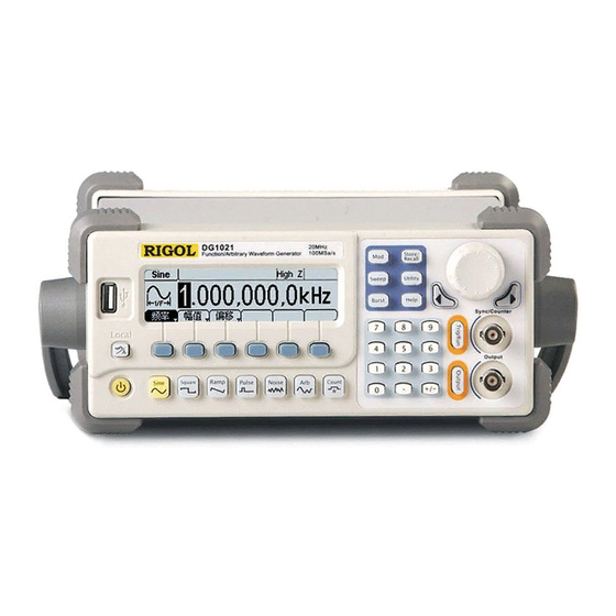
RIGOL RIGOL DG1000 Generator at a Glance This guide covers the following two types of DG1000 Series Function/ Arbitrary Waveform Generators: DG1021、DG1011 RIGOL DG1000 Series Function/ Arbitrary Waveform Generator adopt the DDS technology, which can provide stable, high-precision, pure and low distortion sine signal. - Page 8 All the indexes described in this guide are according to DG1021, if you need to know the particular specifications about the other type, please look over “Appendix A” in Chapter 6. © Copyright RIGOL Technologies, Inc. 2007 User’s Guide for DG1000 Series...
-
Page 9: Table Of Contents
RIGOL Content Safety Notices ........................II RIGOL DG1000 Generator at a Glance................V Chapter 1 Getting Started..................1-1 General Inspection ......................1-2 Handle Adjustment......................1-3 The Front/Rear Panel....................... 1-4 The DG1000 User Interface .................... 1-7 To Set a Waveform ......................1-8 To Set Modulate/ Sweep/Burst.................. - Page 10 Chapter 5 Support & Service................. 5-1 Chapter 6 Appendix....................6-1 Appendix A Specifications....................6-1 Appendix B DG1000 Series Accessories ................ 6-9 Appendix C General Care and Cleaning............... 6-10 © Copyright RIGOL Technologies, Inc. 2007 VIII User’s Guide for DG1000 Series...
-
Page 11: Chapter 1 Getting Started
Chapter 1 Getting Started This chapter covers the following topics: General Inspection To Adjust the Handle The Front/rear Panel of DG1000 Series The User Interface of DG1000 Series To Set a Waveform To Set Modulation/Sweep/Burst To Set Trigger/Output and Counter... -
Page 12: General Inspection
RIGOL General Inspection When you get a new DG1000 Series Function/ Arbitrary Waveform Generator, you are suggested to take the following steps to inspect the instrument. 1. Inspect the shipping container for damage. If there are damages in the packing or foam, keep them until he whole machine and the accessories passing the electric and mechanical testing. -
Page 13: Handle Adjustment
Then, make the handle rotate to the desired position. The operating methods are shown below in graphs 1-1 and 1-2. Figure 1-1 The method of adjusting the handle Figure 1-2 Adjustable Positions © Copyright RIGOL Technologies, Inc. 2007 User’s Guide for DG1000 Series... -
Page 14: The Front/Rear Panel
RIGOL The Front/Rear Panel When you get a new DG1000 Series Function/ Arbitrary Waveform Generator, first you need to know how to operate the front/ Rear panel correctly. This chapter will make a brief introduction and description for the operation and functions of the Front/ Rear Panel. - Page 15 RIGOL Figure 1-4 Front Panel Operation Instruction for DG1000 Series The Rear Panel at a Glance Figure 1-5 Rear Panel for DG1000 Series © Copyright RIGOL Technologies, Inc. 2007 User’s Guide for DG1000 Series...
- Page 16 RIGOL Figure 1-6 Rear Panel Operation Instruction for DG1000 Series © Copyright RIGOL Technologies, Inc. 2007 User’s Guide for DG1000 Series...
-
Page 17: The Dg1000 User Interface
RIGOL The DG1000 User Interface DG1000 Series Function/ Arbitrary Waveform Generator provide two Display modes: Menu and Graph. Under the Menu Display mode, the display interface is divided into 4 parts: state, waveform icon, operation menu, and parameter display. See Figure 1-7. -
Page 18: To Set A Waveform
Waveform Selection Buttons 1. Press Sine button, and the waveform icon turns into Sine with a “Sine” typeface in the state area. DG1000 Series Generator can generate Sine signal with frequency from 1μHz to 20MHz. By setting Frequency/Period, Amplitude/ High Level, Offset/ Low level, sine signal with different parameters can be generated. - Page 19 Offset and 50% Duty Cycle. 3. Press Ramp button, and the waveform icon turns into Ramp with a “Ramp” typeface in the state area. DG1000 Series Generator can generate Ramp signal with frequency from 1μHz to 150 kHz and variable Symmetry. By setting Frequency/Period, Amplitude/ High Level, Offset/ Low level, and Symmetry, Ramp signal with different parameters can be generated.
- Page 20 Offset. 6. Press Arb button, and the waveform icon turns into Arb with an “Arb” typeface in the state area. DG1000 Series Generator can generate repeatable arbitrary waveform signals with at most 4K points and 3MHz frequency. By setting Frequency/Period, Amplitude/ High Level, Offset/ Low level, arbitrary waveform signals with different parameters can be generated.
-
Page 21: To Set Modulate/ Sweep/Burst
Type, Internal/external Modulation, Depth, Frequency, Waveform, etc. DG1000 Series can modulate waveform using AM, FM, PM and FSK. Sine, Square, Ramp or Arbitrary waveforms can be modulated (Pulse, Noise and DC cannot be modulated). - Page 22 Burst can last for certain times of waveform cycle (N-Cycle Burst) or be controlled by external gated signals (Gated Burst). Burst applies to all kinds of waveforms, but noise can only be used in gated burst. © Copyright RIGOL Technologies, Inc. 2007 1-12 User’s Guide for DG1000 Series...
-
Page 23: To Set Trigger/Output
2. Press Output Button, activate or deactivate the output signal. If an overload message is shown, disconnect the external equipment from the output terminals and press Output button, reactivate the output terminal. © Copyright RIGOL Technologies, Inc. 2007 1-13 User’s Guide for DG1000 Series... -
Page 24: To Use Digital Input
1. Use the Direction keys to move the cursor left or right. Rotate the knob to change a digit (clockwise to increase). 2. Use the Keypad to set the parameters values of the waveforms, which can change its value directly. © Copyright RIGOL Technologies, Inc. 2007 1-14 User’s Guide for DG1000 Series... -
Page 25: To Use Store/Utility/Help Function
Operation Instruction To get help: To get help on any key of the front panel, press the key and last for 1 second, then the help message will appear. © Copyright RIGOL Technologies, Inc. 2007 1-15 User’s Guide for DG1000 Series... -
Page 27: Chapter 2 Operating Your Generator
RIGOL Chapter 2 Operating Your Generator By now you have got a brief understanding of DG1000 series with the front/rear panel, every function control area and keys. You should also know how to set your function/ arbitrary waveform generator. If you are not familiar with these operations, please read Chapter 1 “Getting Started”... -
Page 28: The Menu/Graph Mode
Menu Figure 2-2 Setting the parameters in the Graph Mode To Quit the Graph Mode To quit the Graph Mode, press the / A and return the Menu Mode. © Copyright RIGOL Technologies, Inc. 2007 User’s Guide for DG1000 Series... -
Page 29: To Set Sine Signals
Amplitude/ High Level current parameter will switch at a second press. Offset/Low Setting the signal’s Offset or Low Level; the Level current parameter will switch at a second press © Copyright RIGOL Technologies, Inc. 2007 User’s Guide for DG1000 Series... - Page 30 When using the knob to input, use the direction buttons to select the digit you want to edit and rotate the knob to change its value. © Copyright RIGOL Technologies, Inc. 2007 User’s Guide for DG1000 Series...
- Page 31 (2) Input the desired Amplitude Use the keypad or the knob to input the desired value, choose the unit, and press the corresponding button. Current Parameter: Amplitude Figure 2-6 Setting the Amplitude © Copyright RIGOL Technologies, Inc. 2007 User’s Guide for DG1000 Series...
- Page 32 Figure 2-8 Waveform Parameter in the Graph Mode Notes: the Setting of any waveform for DC Offset is the same as sine wave, so we will not cover this topic hereon. © Copyright RIGOL Technologies, Inc. 2007 User’s Guide for DG1000 Series...
-
Page 33: To Set Square Signals
Offset/Low Setting the signal’s Offset or Low Level; the Level current parameter will switch at a second press Duty Cycle Setting the Duty Cycle for Square Waveform © Copyright RIGOL Technologies, Inc. 2007 User’s Guide for DG1000 Series... - Page 34 Duty Cycle: The percentage that the High Level takes up in the whole Period. Please Note : for the Frequency Duty Cycle Value Below 3MHz(included): 20% to 80% From 3MHz to 4MHz (included): 40% to 60% From 4MHz to 5MHz (included): © Copyright RIGOL Technologies, Inc. 2007 User’s Guide for DG1000 Series...
- Page 35 Current Parameter: Duty Cycle Figure 2-11 Setting the Duty Cycle In the Graph Mode, the waveform is shown in Figure 2-12. Figure 2-12 Waveform Parameters in the Graph Mode © Copyright RIGOL Technologies, Inc. 2007 User’s Guide for DG1000 Series...
-
Page 36: To Set Ramp Signals
Symmetry Setting the Symmetry for Ramp Waveform Term Explanation: Symmetry: The percentage that the Rising Period takes up in the whole Period. Input Range: 0~100% © Copyright RIGOL Technologies, Inc. 2007 2-10 User’s Guide for DG1000 Series... - Page 37 The Generator will change the waveform immediately. Current Parameter: Symmetry Figure 2-15 Setting the Symmetry In the Graph Mode, the waveform is shown in Figure 2-16. Figure 2-16 Waveform Parameter in the Graph Mode © Copyright RIGOL Technologies, Inc. 2007 2-11 User’s Guide for DG1000 Series...
-
Page 38: To Set Pulse Signals
Setting the Pulse Width or Duty Cycle for Pulse DtyCyc Waveform. Term Explanation: Pulse Width: The time span between thresholds of 50% of the rising edge amplitude to the next 50% of the falling edge amplitude. © Copyright RIGOL Technologies, Inc. 2007 2-12 User’s Guide for DG1000 Series... - Page 39 For instance, the current period is1ms, the pulse width is 500µs and the duty cycle is 50%, when setting the pulse width to be 200µs, the duty cycle will become 20%. © Copyright RIGOL Technologies, Inc. 2007 2-13 User’s Guide for DG1000 Series...
-
Page 40: To Set Noise Signals
Level current parameter will switch at a second press In the Graph Mode, the waveform is shown in Figure 2-23. Figure 2-23 Waveform Parameter in the Graph Mode © Copyright RIGOL Technologies, Inc. 2007 2-14 User’s Guide for DG1000 Series... -
Page 41: To Set Arbitrary Signals
Setting the signal’s Offset or Low Level; the Level current parameter will switch at a second press. Load Select the built-in Arbitrary Signal as Output. Edit Create and Edit Arbitrary Waveform. © Copyright RIGOL Technologies, Inc. 2007 2-15 User’s Guide for DG1000 Series... - Page 42 When there is no waveform stored in the Non-Volatile Memory, the Stored Menu and the Delete Menu will hide. When there is no waveform in the Volatile Memory, the Volatile menu will hide. © Copyright RIGOL Technologies, Inc. 2007 2-16 User’s Guide for DG1000 Series...
- Page 43 Select the built-in Cardiac Waveform Cancel In the Graph Mode, the waveform is shown in Figure 2-28. Figure 2-28 Waveform Parameter in the Graph Mode (Exponential Rising Waveform) © Copyright RIGOL Technologies, Inc. 2007 2-17 User’s Guide for DG1000 Series...
- Page 44 Instructions: When there is no waveform stored in the Arb1, Arb2, Arb3 and Arb4, this menu will hide (The rest is the same and will not explain again) © Copyright RIGOL Technologies, Inc. 2007 2-18 User’s Guide for DG1000 Series...
- Page 45 Recall information in the specific position in the memory. Save the waveform to the Store appointed place Remove any waveform that Remove has been stored in the memory © Copyright RIGOL Technologies, Inc. 2007 2-19 User’s Guide for DG1000 Series...
- Page 46 When there is no waveform stored in the Non-Volatile Memory, the Stored Menu and the Delete Menu will hide. When there is no waveform in the Volatile Memory, the Volatile menu will hide. © Copyright RIGOL Technologies, Inc. 2007 2-20 User’s Guide for DG1000 Series...
- Page 47 Activate the linear Interpolation between the Interp On/ defined points Deactivate the linear Interpolation between the defined points Set the number of points when Initializing Points the waveform EditPt Start the Waveform Editor © Copyright RIGOL Technologies, Inc. 2007 2-21 User’s Guide for DG1000 Series...
- Page 48 Creat EditPt, The waveform can be defined by setting the time and voltage for each point using this function. The interface is as follows: Figure 2-34 Operation Menu © Copyright RIGOL Technologies, Inc. 2007 2-22 User’s Guide for DG1000 Series...
- Page 49 Remove the current point Save the created waveform to the Save non-Volatile Memory. Instruction: The time for the last definable point should be less than the cycle period in the waveform. © Copyright RIGOL Technologies, Inc. 2007 2-23 User’s Guide for DG1000 Series...
- Page 50 To save the Arbitrary Waveform: In the Non-volatile Memory, each waveform storage place can only save one waveform. If a new one is stored, the old one will be erased. © Copyright RIGOL Technologies, Inc. 2007 2-24 User’s Guide for DG1000 Series...
- Page 51 RIGOL In the Graph Mode, the waveform is shown in Figure 2-36. The default Arbitrary Waveform Figure 2-36 Waveform Parameter in the Graph Mode © Copyright RIGOL Technologies, Inc. 2007 2-25 User’s Guide for DG1000 Series...
- Page 52 Press Arb Edit Delete, to delete a waveform. Select the desired waveform to be deleted which will be displayed in inverse color and press Remove to delete it. © Copyright RIGOL Technologies, Inc. 2007 2-26 User’s Guide for DG1000 Series...
-
Page 53: To Set Counter
PWidth the signal to be measure Display the negative width of NWidth the signal to be measure measurement parameters of the counter Setup (Coupling way, sensitivity, trig level) © Copyright RIGOL Technologies, Inc. 2007 2-27 User’s Guide for DG1000 Series... - Page 54 For example, the current mode is “AC”, press the key, then the mode will be “DC”. Figure 2-40 To set the coupling mode © Copyright RIGOL Technologies, Inc. 2007 2-28 User’s Guide for DG1000 Series...
- Page 55 Suggest: For low amplitude signal, the “medium” or “high” sensitivity should be used. and for low frequency signal with high amplitude and slower rising edge, low sensitivity is a better choice. Figure 2-41 To set the sensitivity © Copyright RIGOL Technologies, Inc. 2007 2-29 User’s Guide for DG1000 Series...
- Page 56 Figure 2-42 To set the trig level Note: In the DC coupling mode, users are need to adjust the trig level manually. © Copyright RIGOL Technologies, Inc. 2007 2-30 User’s Guide for DG1000 Series...
- Page 57 To measure high frequency signal higher than 1kHz, you should put off the high frequency restrain. © Copyright RIGOL Technologies, Inc. 2007 2-31 User’s Guide for DG1000 Series...
-
Page 58: To Generate The Modulated Waveform
RIGOL To Generate the Modulated Waveform Use the Mod button to generate modulated waveform. DG1000 Series can generate AM, FM, FSK, PM modulated waveforms. The modulation parameters should be set in different types of modulation. For example, In AM, users can set the Source (Internal/ External), depth, Modulating Frequency, Modulating Waveform and Carrier Waveform;... - Page 59 Frequency Range: 2mHz~ AMFreq 20kHz (Only Internal). Sine Square Choose the modulating Waveform. To Triangle change the Carrier Waveform Shape UpRamp DnRamp parameter, press Sine , Square etc. Noise © Copyright RIGOL Technologies, Inc. 2007 2-33 User’s Guide for DG1000 Series...
- Page 60 . For an external source, the depth of AM is controlled by the voltage level of the connector connected to the [Modulation In]. +5V corresponds to the currently set depth. © Copyright RIGOL Technologies, Inc. 2007 2-34 User’s Guide for DG1000 Series...
- Page 61 Frequency Range: 2mHz~ FMFreq 20kHz (Internal Source Only). Sine Square Triangle Press the function key Sine, Square Shape UpRamp etc. to choose different Shape of DnRamp waveform. Noise © Copyright RIGOL Technologies, Inc. 2007 2-35 User’s Guide for DG1000 Series...
- Page 62 Connector connected to the [Modulation In]. +5V corresponds to the selected Deviation. Lower external voltage generates less deviation, while negative voltage reduces the modulated signal frequency to below the corresponding carrier’s. © Copyright RIGOL Technologies, Inc. 2007 2-36 User’s Guide for DG1000 Series...
- Page 63 Hop frequency. Figure 2-51 FSK Waveform Parameter Setting Interface Press Mod Type FSK, enter the following interface. Figure 2-52 Operation Menu © Copyright RIGOL Technologies, Inc. 2007 2-37 User’s Guide for DG1000 Series...
- Page 64 FSK Rate (Internal Modulation Only): 2mHz~ 50kHz. In the Graph Mode, the waveform is shown in Figure 2-53. FSK Frequency Figure 2-53 Waveform Parameter in the Graph Mode © Copyright RIGOL Technologies, Inc. 2007 2-38 User’s Guide for DG1000 Series...
- Page 65 Freq frequency. Frequency Range: 2mHz~ 20kHz (Internal source Only). Sine Square Triangle Press the function key Sine、Square Shape UpRamp etc. to choose different Shape of DnRamp waveform. Noise © Copyright RIGOL Technologies, Inc. 2007 2-39 User’s Guide for DG1000 Series...
- Page 66 RIGOL In the Graph Mode, the waveform is shown in Figure 2-56. Modulating Frequency Phase Deviation Figure 2-56 Waveform Parameter in the Graph Mode © Copyright RIGOL Technologies, Inc. 2007 2-40 User’s Guide for DG1000 Series...
-
Page 67: To Generate Sweep
Press Sweep button, in the Normal Mode, the operation menu will appear on the bottom of the screen, see Figure 2-58. Set the Waveform parameters by using the operation menu. Figure 2-58 Operation Menu © Copyright RIGOL Technologies, Inc. 2007 2-41 User’s Guide for DG1000 Series... - Page 68 Manual: Choose External Source, set the start and stop time by hand Trigger : Signal Triggered at Rise Edge TrigOut : Signal Triggered at Fall Edge Off: Turn off Trigger Setting Finish Setting © Copyright RIGOL Technologies, Inc. 2007 2-42 User’s Guide for DG1000 Series...
- Page 69 To Sweep upward, set the Start Frequency lower than the Stop Frequency, or set a positive frequency interval. To Sweep downward, set the Start Frequency higher than the Stop Frequency, or set a negative frequency interval. © Copyright RIGOL Technologies, Inc. 2007 2-43 User’s Guide for DG1000 Series...
-
Page 70: To Generate Burst
Press Burst button, in the Normal Mode, the operation menu will appear on the screen, see Figure 2-59. Set the Waveform parameters by using the operation menu. Figure 2-59 Burst Waveform Parameter Setting Interface © Copyright RIGOL Technologies, Inc. 2007 2-44 User’s Guide for DG1000 Series... - Page 71 Manual: Choose External Source, set the start and stop time by hand Trigger : Signal Triggered at Rise Edge TrigOut : Signal Triggered at Fall Edge Off: Turn off Trigger Setting Finish Setting © Copyright RIGOL Technologies, Inc. 2007 2-45 User’s Guide for DG1000 Series...
- Page 72 0. In the Graph Mode, the waveform is shown in Figure 2-61. Burst Period Start Phase Delay N-Cycle Cycle Times Figure 2-61 Waveform Parameter in the Graph Mode © Copyright RIGOL Technologies, Inc. 2007 2-46 User’s Guide for DG1000 Series...
- Page 73 Set the Start Phase for the Gated Phase Signal In the Graph Mode, the waveform is shown in Figure 2-63. Start Phase Positive Gated Signal Gated Figure 2-63 Waveform Parameter in the Graph Mode © Copyright RIGOL Technologies, Inc. 2007 2-47 User’s Guide for DG1000 Series...
-
Page 75: To Store And Recall
Remove any waveform that Remove has been stored in the memory About the Disk Use the Disk button to choose Local or U Disk (When U Disk is connected). © Copyright RIGOL Technologies, Inc. 2007 2-49 User’s Guide for DG1000 Series... - Page 76 There are four positions in the Local STATE1, STATE2, STATE3 and STATE4, choose one of them by rotating the knob. (3) Name the file and Save it Press Store button, enter the desired name. Press Store to finish. © Copyright RIGOL Technologies, Inc. 2007 2-50 User’s Guide for DG1000 Series...
- Page 77 There are four positions in the Local ARB1, ARB2, ARB3 and ARB4, choose one of them by rotating the knob. (3) Name the file and Save Press Store button, enter the desired name. Press Store to finish. © Copyright RIGOL Technologies, Inc. 2007 2-51 User’s Guide for DG1000 Series...
- Page 78 (3) Uninstall the mobile Storage Remove the U Disk from the Interface and the system will inform you that the U Disk has been removed, and the “ ” Sign will disappear. © Copyright RIGOL Technologies, Inc. 2007 2-52 User’s Guide for DG1000 Series...
- Page 79 Menu English Input Lang Chinese Input Select Select the current character Remove Delete the current character Store Store the file with the current name Cancel the current operation © Copyright RIGOL Technologies, Inc. 2007 2-53 User’s Guide for DG1000 Series...
- Page 80 When you have entered a wrong character, move the cursor to the wrong character and press Remove to delete it. And then enter the file name again. (4) Press Store, to finish and save the file. © Copyright RIGOL Technologies, Inc. 2007 2-54 User’s Guide for DG1000 Series...
- Page 81 When a file name is wrong, move the cursor to the character and press Remove to delete it and enter the file name again. (5) Press Store to finish and save the file. © Copyright RIGOL Technologies, Inc. 2007 2-55 User’s Guide for DG1000 Series...
-
Page 82: To Set The Utility Function
Press Utility to enter the Utility Menu. Its functions are listed below in table 2-26. Figure 2-71 Operation Menu © Copyright RIGOL Technologies, Inc. 2007 2-56 User’s Guide for DG1000 Series... - Page 83 When the amplitude is low relatively, you can reduce the distortion when output the signal by prohibiting the Sync Signal. And the current storage is in the Non-Volatile Memory. © Copyright RIGOL Technologies, Inc. 2007 2-57 User’s Guide for DG1000 Series...
- Page 84 The DC option is turned off automatically. In the Graph Mode, the waveform is shown in Figure 2-73. Offset Figure 2-73 Waveform Parameter in the Graph Mode © Copyright RIGOL Technologies, Inc. 2007 2-58 User’s Guide for DG1000 Series...
- Page 85 Level High. For External Modulation, the Sync Signal reference is the Carrier Signal (not the Modulated Signal). The Sync Signal is also a Square Waveform with 50% Duty Cycle. © Copyright RIGOL Technologies, Inc. 2007 2-59 User’s Guide for DG1000 Series...
- Page 86 But, please note that this signal will not turn Level Low until the last period end (If the Waveform has a relative starting phase, it may be not intersections). © Copyright RIGOL Technologies, Inc. 2007 2-60 User’s Guide for DG1000 Series...
- Page 87 Select Hold, prohibit the auto optimizing. This will eliminate the” burr” caused by the switch of the Attenuator. But, the precision and the resolution (the fidelity of the original waveform) may be affected. © Copyright RIGOL Technologies, Inc. 2007 2-61 User’s Guide for DG1000 Series...
- Page 88 Figure 2-75 Set the Output Load Instruction DG1000 Series have a fixed 50Ω Series impedance no matter what value has been set for this parameter. If the real load is different from the set one, the displayed voltage will not equal to the real voltage.
- Page 89 Figure 2-77 Inverse Waveform To Adjust the Phase Press Utility Output Phase, enter the following interface. Set the Phase use the unit of degree. Figure 2-78 Setting the Phase © Copyright RIGOL Technologies, Inc. 2007 2-63 User’s Guide for DG1000 Series...
- Page 90 To Set the I/O Press Utility I/O, to set the I/O. See Figure 2-79. Figure 2-79 Operation Menu Table 2-28 I/O Setting Menu Function Settings Explanation Menu USB ID=usb0::2391::1031::MY44005 582::INSTK © Copyright RIGOL Technologies, Inc. 2007 2-64 User’s Guide for DG1000 Series...
- Page 91 Latest: When the power is on, all the setting Setting will return to the latest setting. Default Return all the setting into the default one Timer Choose the clock source as: internal/external © Copyright RIGOL Technologies, Inc. 2007 2-65 User’s Guide for DG1000 Series...
- Page 92 Activate or deactivate the sound when an error occurs from the front panel or the remote interface. Activate or deactivate any sound made by the button or knob on the front panel. © Copyright RIGOL Technologies, Inc. 2007 2-66 User’s Guide for DG1000 Series...
- Page 93 RIGOL Language Setting The DG1000 Series Generator offers two languages: Chinese and English. To Select Language, press Utility and then Lang to select the language. Press Utility System Lang, change the language. Figure 2-81 Language Setting Menu Display Control Press Utility System Display, enter the following menu.
- Page 94 On, the example is as follows: Figure 2-84 Setting the data format (2) “ ” as decimal, press Separat. On, the example is as follows: Figure 2-85 Setting the data format © Copyright RIGOL Technologies, Inc. 2007 2-68 User’s Guide for DG1000 Series...
- Page 95 Space, the example is as follows: Figure 2-88 Setting the data format (6) “ ” as decimal, press Separat. Space, the example is as follows: Figure 2-89 Setting the data format © Copyright RIGOL Technologies, Inc. 2007 2-69 User’s Guide for DG1000 Series...
- Page 96 AM Depth FM Deviation 100Hz FSK Hop Frequency 10Hz FSK Frequency 100Hz Modulation State Sweep Default Start/Stop Frequency 100Hz/1kHz Time Mode Linear State Burst Default Frequency 1kHz Count 1Cycle © Copyright RIGOL Technologies, Inc. 2007 2-70 User’s Guide for DG1000 Series...
- Page 97 Storage State and any No change Waveform Output State Trigger Default Source Internal Calibration Default State Coded The parameter with an asterisk (*) is stored in the Non-Volatile Memory. © Copyright RIGOL Technologies, Inc. 2007 2-71 User’s Guide for DG1000 Series...
- Page 98 Input the password for Secure calibration Perform the Calibration Turn On Secure Setting, disables the calibration by anyone SecOn SecOff Turn Off Secure Setting, enables the calibration by anyone © Copyright RIGOL Technologies, Inc. 2007 2-72 User’s Guide for DG1000 Series...
- Page 99 “12345”. It is stored in the Non-Volatile Memory, and will not change when the instrument is powered off or the Remote I/O is reset. Figure 2-92 Operation Menu © Copyright RIGOL Technologies, Inc. 2007 2-73 User’s Guide for DG1000 Series...
-
Page 100: How To Use The Built-In Help System
Table 2-34 Help Menu Function Settings Explanation Menu Select Select and read the Information Page Up Page Down Cursor Downward to select Cursor Upward to select Exit the help menu © Copyright RIGOL Technologies, Inc. 2007 2-74 User’s Guide for DG1000 Series... - Page 101 Make sure that the time value of the last point less than the specified period. (5) Press Save to store the waveform and exit the waveform editor. © Copyright RIGOL Technologies, Inc. 2007 2-75 User’s Guide for DG1000 Series...
- Page 102 By using the external I/O of the generator, connect the instrument to the other kinds of instruments, to perform the synchronous control. 9.RIGOL Technology Support To obtain technical support, contract the local RIGOL Support Center or go to RIGOL website: www.rigol.com Consult Chapter 5 for more details.
-
Page 103: Chapter 3 Application & Examples
”, The Offset is set to be 0 When the Frequency, Amplitude and Offset were set, the generated waveform is shown in Figure 3-1. Figure 3-1 Sine Waveform Output © Copyright RIGOL Technologies, Inc. 2007 User’s Guide for DG1000 Series... -
Page 104: Example 2: To Generate A Square Wave
(2) Enter “30” from the keypad and choose the unit “%” to set the Duty Cycle as 30%. When the Frequency, Amplitude Offset and Duty Cycle were set, the generated waveform is shown in Figure 3-2. Figure 3-2 Square Waveform Output © Copyright RIGOL Technologies, Inc. 2007 User’s Guide for DG1000 Series... -
Page 105: Example 3: To Generate A Ramp Wave
(2) Enter “80” from the keypad and choose the unit “%” to set the Symmetry as 80%. When the Frequency, Amplitude Offset and Symmetry were set, the generated waveform is shown in Figure 3-3. Figure 3-3 Ramp Waveform Output © Copyright RIGOL Technologies, Inc. 2007 User’s Guide for DG1000 Series... -
Page 106: Example 4: To Generate A Pulse Wave
(2) Enter “20” from the keypad and choose the unit “μs” to set the Pulse Width as 20μs. When the Frequency, High Level, Low Level and Pulse Width were set, the generated waveform is shown in Figure 3-4. Figure 3-4 Pulse Waveform Output © Copyright RIGOL Technologies, Inc. 2007 User’s Guide for DG1000 Series... -
Page 107: Example 5: To Generate A Noise Wave
(2) Enter “10” from the keypad and choose the unit “mV ” to set the Offset as 10mV When the Amplitude and Offset were set, the generated waveform is shown in Figure 3-5. Figure 3-5 Noise Waveform Output © Copyright RIGOL Technologies, Inc. 2007 User’s Guide for DG1000 Series... -
Page 108: Example 6: To Generate Arbitrary Waveform
Right now, the selected waveform is appointed to Arb. This waveform will put out once the key is pressed. Press Arb to confirm what kind of waveform is selected. © Copyright RIGOL Technologies, Inc. 2007 User’s Guide for DG1000 Series... -
Page 109: Example 7: To Generate An Arbitrary Waveform
4. Set the Number of the initializing Points. Set the Initializing Point Number as “4”. 5. Choose the Interpolation Method. Press Interp. Interpation On, to perform linear connection between the points. © Copyright RIGOL Technologies, Inc. 2007 User’s Guide for DG1000 Series... - Page 110 If a new one is stored, the old one will be erased. The waveform is generated through the steps above. The waveform is shown in Figure 3-8. Figure 3-8 The Self-Defined Ramp Waveform © Copyright RIGOL Technologies, Inc. 2007 User’s Guide for DG1000 Series...
-
Page 111: Example 8: To Generate An Am Waveform
6. Choose the Modulating Waveform. Press Shape Sine, to choose Sine Waveform as the Modulating Waveform. Please note that the State Message on the top left side of the screen shows “Sine”. © Copyright RIGOL Technologies, Inc. 2007 User’s Guide for DG1000 Series... - Page 112 At this time, the instrument generates the specified AM waveform. The Waveform is shown in Figure 3-9. Figure 3-9 The AM Output 7. Turn off the Modulation Function. Press the lighted Mod Key to turn off the Modulation Function. © Copyright RIGOL Technologies, Inc. 2007 3-10 User’s Guide for DG1000 Series...
-
Page 113: Example 9: To Generate An Fsk Waveform
Press HopFreq, use the keypad to enter “800”, choose the unit “Hz”, setting the Hop Frequency as 800Hz. At this time, the instrument generates the specified AM waveform. The Waveform is shown in Figure 3-10. Figure 3-10 The FSK Output © Copyright RIGOL Technologies, Inc. 2007 3-11 User’s Guide for DG1000 Series... - Page 114 RIGOL 6. Turn off the Modulation Function. Press the lighted Mod Key to turn off the Modulation Function. © Copyright RIGOL Technologies, Inc. 2007 3-12 User’s Guide for DG1000 Series...
-
Page 115: Example 10: To Generate A Linear Sweep Waveform
Frequency as 100Hz. 6. Set the Stop Frequency. Press Stop, use the keypad to enter “10”, choose the unit “kHz”, to set the Stop Frequency as 10 kHz. © Copyright RIGOL Technologies, Inc. 2007 3-13 User’s Guide for DG1000 Series... - Page 116 These parameters are similar to the Start and Stop frequency, which will provide more flexibility for you. To generate the same waveform, set the Center Frequency to be 5.050 kHz, the frequency range is 9.900 kHz. © Copyright RIGOL Technologies, Inc. 2007 3-14 User’s Guide for DG1000 Series...
-
Page 117: Example 11: To Generate A Burst Waveform
Press Phase, use the keypad to enter “0”, choose the unit “°”, setting the Start phase as 0°. 6. Set the Burst Cycles. Press Cycles, use the keypad to enter “3”, choose the unit “Cyc”, setting the Burst Cycle as 3. © Copyright RIGOL Technologies, Inc. 2007 3-15 User’s Guide for DG1000 Series... - Page 118 At this time, the instrument generates the specified 3- Cycle Burst waveform with a period of 10ms. The waveform is shown in Figure 3-12. Figure 3-12 The Burst Waveform Output © Copyright RIGOL Technologies, Inc. 2007 3-16 User’s Guide for DG1000 Series...
-
Page 119: Example 12: To Measure The Frequency
If the reading is unsteady, please repeat the above step until it is steady. To view the result. (1) Frequency view: In default state, the measure result is frequency value, see figure 3-13; Figure 3-13 © Copyright RIGOL Technologies, Inc. 2007 3-17 User’s Guide for DG1000 Series... - Page 120 (4) Positive width view: press PWidth, the positive width will display as figure 3-16; Figure 3-16 (5) Negative width view: press NWidth, the negative width will display as figure 3-17. Figure 3-17 © Copyright RIGOL Technologies, Inc. 2007 3-18 User’s Guide for DG1000 Series...
-
Page 121: Chapter 4 Prompt Messages & Troubleshooting
Edit the existing waveform parameters. Perform the waveform edit operation, and inform the user that operation can be taken to edit the current waveform parameter. © Copyright RIGOL Technologies, Inc. 2007 User’s Guide for DG1000 Series... - Page 122 When you power a new instrument, the default calibration time is 0. The latest version can be reached at the company’s website: http:// www.rigol.com. © Copyright RIGOL Technologies, Inc. 2007 User’s Guide for DG1000 Series...
- Page 123 Press “Yes” to continue; Press “Cancel” to reselect the place. Can't Write this File to system This message appears when the operation of burning menu or programs into the system from the U Disk fails. © Copyright RIGOL Technologies, Inc. 2007 User’s Guide for DG1000 Series...
- Page 124 If the updating of the System is successful by using the U disk, this message will appear. The instrument has to be restarted to update the settings. It also informs the user that if a technical problem occurs after the updating, contact the RIGOL technician for support.
- Page 125 Initial # of points upper limit=4K The upper limit of the initial points is 4,096. If the specified waveform has more than 4,096 points, the system will adjust the number to 4,096 automatically. © Copyright RIGOL Technologies, Inc. 2007 User’s Guide for DG1000 Series...
- Page 126 If the gated burst mode is activated and the burst is also activated, no “Trigger Output” is allowed. Frequency is set maximum for Arb. The maximum frequency for the arbitrary waveform is 5MHz. when a waveform of © Copyright RIGOL Technologies, Inc. 2007 User’s Guide for DG1000 Series...
- Page 127 Modulation has been turned off to allow Pulse. Pulse, noise and DC are not allowed to generate modulated waveform. So the modulation has to be turned off to allow Pulse. © Copyright RIGOL Technologies, Inc. 2007 User’s Guide for DG1000 Series...
- Page 128 Deviation has been changed due to carrier frequency. The Carrier frequency should always be greater than or equal to the deviation © Copyright RIGOL Technologies, Inc. 2007 User’s Guide for DG1000 Series...
- Page 129 The generator can not use DC Voltage function to generate Burst. Burst has been turned off to allow DC. The generator can not use DC to generate Burst. So the Burst is turned off. © Copyright RIGOL Technologies, Inc. 2007 User’s Guide for DG1000 Series...
- Page 130 The Arb wave frequency lower limit is 1μHz. If the specified frequency is lower than 1μHz, the system will adjust the frequency to 1μHz automatically. Sine Wave period upper limit= 1 Ms © Copyright RIGOL Technologies, Inc. 2007 4-10 User’s Guide for DG1000 Series...
- Page 131 Amplitude upper limit= ** Different mode has different amplitude upper limit; amplitude upper limit may vary in the same mode if the load is different. Amplitude lower limit= ** © Copyright RIGOL Technologies, Inc. 2007 4-11 User’s Guide for DG1000 Series...
- Page 132 Different mode has different Offset upper limit; Offset upper limit may vary in the same mode if the load is different. Offset lower negative limit = ** Different mode has different Offset lower limit; Offset lower limit may vary in the © Copyright RIGOL Technologies, Inc. 2007 4-12 User’s Guide for DG1000 Series...
- Page 133 120.0%, the system will adjust the AM Depth to 120.0% automatically. AM Depth lower limit = 0.0%. The AM Depth lower limit is 0.0%. If the specified AM Depth is less than 0.0%, the © Copyright RIGOL Technologies, Inc. 2007 4-13 User’s Guide for DG1000 Series...
- Page 134 PM Frequency lower limit= 2mHz The PM Frequency lower limit is 2mHz. If the specified PM Frequency is lower than 2mHz, the system will adjust the PM Frequency to 2mHz automatically. © Copyright RIGOL Technologies, Inc. 2007 4-14 User’s Guide for DG1000 Series...
- Page 135 -19.999,998 MHz; If the Carrier is a Ramp wave, the Center Frequency lower limit is -149.999,99 kHz; If the Carrier is an Arb wave, the Center Frequency lower © Copyright RIGOL Technologies, Inc. 2007 4-15 User’s Guide for DG1000 Series...
- Page 136 0.0000000000s, the system will adjust the Delay to 0.0000000000s automatically Load Impedance upper limit =10kΩ The Load Impedance upper limit is 10kΩ. If the specified Load Impedance is greater © Copyright RIGOL Technologies, Inc. 2007 4-16 User’s Guide for DG1000 Series...
- Page 137 . If the specified Start Phase is less than -360.0 the system will adjust the Start Phase to -360.0 automatically. (**denotes the parameter, the content of which will vary according to the setting.) © Copyright RIGOL Technologies, Inc. 2007 4-17 User’s Guide for DG1000 Series...
-
Page 138: Troubleshooting
② Check if the power switch is really on. ③ Restart the instrument after taking the above steps. ④ If it does not work correctly, contact RIGOL for our service. 2. If the settings are correct but no waveform is generated, please follow the steps below: ①... -
Page 139: Chapter 5 Support & Service
Chapter 5 Support & Service Warranty RIGOL warrants that the products it manufactured and sold will be free from defects in materials and workmanship for a period of three years from the date of shipment from an authorized RIGOL distributor. If a product proves defective within the guarantee period, RIGOL will provide repair or replacement as described in the complete warranty statement. - Page 140 RIGOL Contact RIGOL If you meet any ambiguity during operating our products, please contact RIGOL Technologies, Inc. or contact your local distributor. Domestic: Please call Tel: (8610)80706688 Fax: (8610)80720067 9:00 am –5: 00 pm from Monday to Friday Or by e-mail: support@rigol.com...
-
Page 141: Chapter 6 Appendix
RIGOL Chapter 6 Appendix Appendix A Specifications All the specifications apply to the DG1000 Series Function/ Arbitrary Waveform Generator unless specified statement. To meet these specifications, two conditions must be satisfied first: ■ The instrument must have operated continuously for more than 30 minutes within the specified operating temperature. - Page 142 5MHz bandwidth (-3dB) White Noise 1µHz to 4MHz Resolution 1 µHz Accuracy Within 90 days: 10 ppm Within 1 year: 20 ppm, 18°C - 28°C Temperature index < 2 ppm/°C © Copyright RIGOL Technologies, Inc. 2007 User’s Guide for DS1000 Series...
- Page 143 < 0.1% of peak output Symmetry 0% to 100% Pulse Wave Characteristics Pulse Width 2000s max period;20ns min period; 10ns resolution Overshoot < 2% Jitter 6ns + 100ppm of period © Copyright RIGOL Technologies, Inc. 2007 User’s Guide for DG1000 Series...
- Page 144 Short-circuit protected; Overload disables the output automatically AM Modulation Carrier Waveforms Sine, Square, Ramp, Arb Source Internal/ External Modulating Waveforms Sine, Square, Ramp, Noise, Arb (2mHz to 20kHz) Depth 0% - 120% © Copyright RIGOL Technologies, Inc. 2007 User’s Guide for DS1000 Series...
- Page 145 1 µs – 500s ± 1% Gate Source External Trigger Trigger Source Internal/External/Manual Rear Panel Connector External AM Modulation ± 5 V = 100% modulation 5kΩ input impedance External Trigger TTL-compatible © Copyright RIGOL Technologies, Inc. 2007 User’s Guide for DG1000 Series...
- Page 146 ~ 10 V Duty cycle measure Input impedance 1MΩ AC、DC Coupling mode Input adjust High frequency noise restrain High frequency restrain (HFR) on or off sensitivity Low, Medium, High © Copyright RIGOL Technologies, Inc. 2007 User’s Guide for DS1000 Series...
- Page 147 RIGOL The trigger level can adjust manually/ automatically Trigger mode Trigger level range: ±3 V (0.1% to 100%) Resolution: 6 mV © Copyright RIGOL Technologies, Inc. 2007 User’s Guide for DG1000 Series...
- Page 148 Operation : below 3,000m Non-operation: below 15,000m Instrument Specifications Dimension Width 232mm Height 108mm Depth 288mm Weight Package 2.65 Kg excluded Package Included IP Protection IP2X Calibration Interval One year suggested © Copyright RIGOL Technologies, Inc. 2007 User’s Guide for DS1000 Series...
-
Page 149: Appendix B Dg1000 Series Accessories
RIGOL Appendix B DG1000 Series Accessories Standard Accessories: A Power Cord that fits the standard of the destination country. USB Data Wire A set of Ultrawave Arbitrary Waveform Edition Software for WIN98/2000/XP A《User’ Guide》 A product service card Optional Accessories:... -
Page 150: Appendix C General Care And Cleaning
Warning: To avoid any short-circuit or body damage because of the moisture, make sure that the instrument is dry before restarting the instrument. © Copyright RIGOL Technologies, Inc. 2007 6-10 User’s Guide for DS1000 Series...
Need help?
Do you have a question about the DG1021 and is the answer not in the manual?
Questions and answers