Table of Contents
Advertisement
Quick Links
Installation and Owner's Manual
WARNING: If the information in these
instructions is not followed exactly, a fi re
or explosion may result causing property
damage, personal injury or loss of life.
Do not store or use gasoline or other
fl ammable vapors and liquids in the vicinity
of this or any other appliance.
WHAT TO DO IF YOU SMELL GAS
• Do not try to light the appliance.
• Do not touch any electrical switch; do not
use any phone in your building.
• Immediately call your gas supplier from
a neighbor's phone. Follow the gas
supplier's instructions.
• If you cannot reach your gas supplier, call
the fi re department.
Installation and service must be performed
by a qualifi ed installer, service agency or the
gas supplier.
4002252-08
©2012, Miles Industries Ltd.
L
EGEND
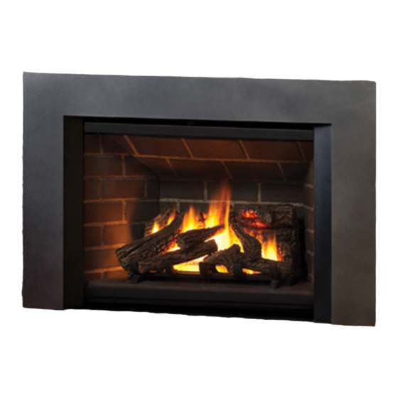
Direct Vent Gas Insert
780IN (NG) & 780IP (LPG)
HOT GLASS WILL
CAUSE BURNS.
DO NOT TOUCH GLASS
UNTIL COOLED.
NEVER ALLOW CHILDREN
TO TOUCH GLASS.
Manufactured by
MILES INDUSTRIES LTD., British Columbia, Canada
www.valorfi replaces.com
G4
IN STA LLER
Leav e t his manua l
with the applia nce .
C ON SU MER
Ret ain this ma nual
for f uture r efe re nce.
Please read this manual BEFORE installing
and operating this appliance.
This appliance may be installed in an
after-market permanently located,
manufactured (mobile) home where not
prohibited by local codes.
This appliance is only for use with the type
of gas indicated on the rating plate. This
appliance is not convertible for use with
other gases, unless a certifi ed kit is used.
This appliance is a domestic room-heating
appliance. It must not be used for any other
purposes such as drying clothes, etc.
This appliance is suitable for installation in a
bedroom or bed sitting room.
Massachusetts: The piping and fi nal
gas connection must be performed by a
licensed plumber or gas fi tter in the State of
Massachusetts.
Ce guide est disponible en français sur demande.
Patent Pending
Advertisement
Table of Contents

Related Manuals for Miles Industries Valor 780IN


Summary of Contents for Miles Industries Valor 780IN
- Page 1 fi tter in the State of by a qualifi ed installer, service agency or the Massachusetts. gas supplier. Ce guide est disponible en français sur demande. Manufactured by MILES INDUSTRIES LTD., British Columbia, Canada www.valorfi replaces.com 4002252-08 ©2012, Miles Industries Ltd.
-
Page 2: Table Of Contents
Window Refi tting..........34 The information contained in this installation manual is believed to be correct at the time of printing. Miles Industries Ltd. reserves the right to change or modify any information or speci- fi cations without notice. Miles Industries Ltd. -
Page 3: Safety Precautions
Safety Precautions READ and UNDERSTAND all instructions carefully This unit MUST be used with a vent system as before starting the installation. FAILURE TO FOLLOW described in this installation manual. NO OTHER vent these installation instructions may result in possible fi re system or components MAY BE USED. -
Page 4: Safety And Your Fireplace
Safety and Your Fireplace Safety and Your Fireplace Please Read and Carefully Follow all Safety Warnings and Operating Instructions Contained in Your Owners Manual (Replacement Manuals are available by contacting our service department at 1-800-468-2567 or visit www.valorfi replaces.com). withdraw in the event of accidental Please Follow These Important contact with a hot surface. -
Page 5: Owner's Information
Owner’s Information INFORMATION Thank You ... WARNING For purchasing a Valor by Miles Industries. Your new EXTREMELY HOT!!! radiant gas heater is a technical appliance that must be installed by a qualifi ed dealer. Each Valor fi replace • READ the SAFETY information on pages... - Page 6 2. While you hold it, pull the particular case. side levers back into the window brackets on each NOTE: This is a problem beyond Miles Industries’ side. control and is not covered under warranty. IMPORTANT: To ensure a safe operation, verify •...
- Page 7 OWNER’S Owner’s Information INFORMATION The appliance area must always be kept clear and Checks free from combustible materials, gasoline and other A periodic check of the pilot and burner fl ames should fl ammable vapors and liquids. be made. Check after the fi re has been on for at least Inspect the vent terminal outdoors regularly to make 30 minutes.
- Page 8 OWNER’S Owner’s Information INFORMATION Batteries Lighting, Operation and Rating Information WARNING WARNING WARNING WARNING DO NOT ATTEMPT TO CHANGE THE BATTER- DO NOT ATTEMPT TO TOUCH THE DATA PLATE IES WHILE THE FIREPLACE IS STILL HOT! Let WHILE THE FIREPLACE IS STILL HOT! Let the the fi...
- Page 9 OWNER’S Owner’s Information INFORMATION (including pilot) How to Turn Your Fireplace OFF Familiarize yourself with each of these methods before operating your fi replace. Handset and Wall Switch: Press and hold the OFF button for a second. If the fl ames are on, they go down and you hear the valve motor wind down.
-
Page 10: Remote Control Operation
OWNER’S Remote Control Operation INFORMATION NOTE: Before using the remote control system for IMPORTANT: BEFORE YOU BEGIN, please note that the fi rst time, the receiver and the handset must be on this system, the settings of time, temperature and synchronized. - Page 11 OWNER’S Remote Control Operation INFORMATION • Press and hold (small fl ame) MODES OF OPERATION button to decrease fl ame height or • Briefl y pressing the SET button to set the appliance at pilot fl ame. changes the mode of operation in •...
- Page 12 OWNER’S Remote Control Operation INFORMATION • SETTING THE ON / OFF TEMPERATURES - Nighttime Setback T E M P Temperature Mode (Appliance must be in standby mode; pilot SETTING THE “DAYTIME” TEMPERATURE ignited) - The room temperature (sun), Default Settings: 23ºC / 74ºF TEMP is measured and compared to the...
- Page 13 OWNER’S Remote Control Operation INFORMATION SETTING THE “NIGHTTIME SETBACK” SETTING PROGRAM TIMERS TEMPERATURE • You can program two periods of time between 12:00 (moon), Default Settings: “ ” (OFF) T E M P am and 11:50 pm in each 24-hour cycle. •...
- Page 14 OWNER’S Remote Control Operation INFORMATION SETTING P1 OFF TIME SETTING P2 ON TIME • Briefl y press SET to scroll to TIMER mode • Briefl y press SET button to scroll (sun) while the time fl ashes. to TIMER (moon) while the •...
-
Page 15: Options
OWNER’S Remote Control Operation INFORMATION LOW BATTERY INDICATION HANDSET / RECEIVER MATCH The remote control handset and receiver are program- CAUTION med to function together. In case of a replacement of DO NOT USE a screwdriver or other metallic object the handset or the receiver, you will need to reset the to remove the batteries from the battery box or the receiver to allow them to function together. -
Page 16: Lighting Instructions
OWNER’S Lighting Instructions INFORMATION FOR YOUR SAFETY, READ BEFORE LIGHTING WARNING : If you do not follow these instructions exactly A. This appliance has a pilot which must be lighted by hand or by remote control. Follow these instructions exactly. To save gas, turn the pilot off when not using the appliance for a prolonged period of time. -
Page 17: Specifi Cations
QUALIFIED Specifi cations INSTALLER Approval & Codes *High Altitude Installations This appliance is certifi ed to ANSI Z21.88-2009 / CSA Input ratings are shown in BTU per hour and are 2.33-2009 American National Standard / CSA Standard certifi ed without deration for elevations up to 4,500 feet for Vented Gas Fireplace Heaters for use in Canada (1,370 m) above sea level. -
Page 18: Overview
QUALIFIED Overview INSTALLER This appliance may ONLY be installed in an existing unaltered, functioning solid-fuel burning fi replace with a working fl ue and constructed of non-combustible material. DO NOT install into combustible construction. This appliance is NOT APPROVED for installation with a zero clearance kit. WARNING WARNING Chimney Terminal Cap... -
Page 19: Dimensions
QUALIFIED Dimensions INSTALLER 33” (838 mm) 24” (610 mm) 6’ (1.9 m) Fan power cord 3” (76 mm) Optional fan 3” 3” 15” (76 mm) (76 mm) (381 mm) 15” 4” Trim (381 mm) (102 mm) (sold separately) 10” Gas line approx. 24“ (610 mm) of flex protruding from (254 mm) sheet metal box... -
Page 20: Clearances
QUALIFIED Clearances INSTALLER WARNING WARNING Some materials or items, although safe, may discolor, shrink, warp, crack, peel, Some materials or items, although safe, may discolor, shrink, warp, crack, peel, and so on because of the heat produced by the fi replace. Avoid placing candles, and so on because of the heat produced by the fi... -
Page 21: Venting
QUALIFIED Venting INSTALLER Typical Vent Installation See list of approved Venting Accessories on page 39 of this manual. NOTE: Flexible co-linear vent pipes may only be installed into existing non-combustible solid-fuel burning fi replaces and chimneys. Terminal Cap Vent Location The vent terminal must be located through the roof. -
Page 22: Installation Planning
QUALIFIED Installation Planning INSTALLER Only qualifi ed licensed or trained personnel should install this appliance. Installer—READ THIS FIRST 13. Refi t window. 1. YOU NEED TO KNOW FROM THE HOMEOWNER what accessories (surround, 14. Reinstall the hot glass warning plate if it has been screen, fan/blower, etc.) will be installed with removed. -
Page 23: Appliance Preparation
QUALIFIED Existing Fireplace Preparation INSTALLER Gas Line Routing Combustible Mantels Plan the routing of the gas line before proceeding. Combustible mantel clearances must conform to those Utilize the existing hole for the gas line of the factory- required for the original solid-fuel fi replace into which built fi... - Page 24 QUALIFIED Appliance Preparation INSTALLER Window Removal The window is held in place by a spring-loaded lever on each side. 1. To remove the window, locate the levers on each side of the window towards the top. Using your fi nger, pull the lever towards you and unhook it from the window frame bracket.
- Page 25 QUALIFIED Appliance Preparation INSTALLER Venting Installation IMPORTANT: This appliance’s venting system is room sealed and therefore, does not require room air to be used in the combustion process. 1. Rough-in two 3” diameter vent liners into the existing chimney system from the roof. Be careful not to tear or damage the liners in the process.
-
Page 26: Supply Gas Installation
QUALIFIED Supply Gas Installation INSTALLER The gas supply inlet connection is a 1/2” NPT female. Pressure Test Points Gas shut-off valve supplied on the end of stainless The minimum supply pressure is given in the steel fl exible connector. Flex connector is located on section Specifi... - Page 27 QUALIFIED Supply Gas Installation INSTALLER Use common elbow and fi ttings (not Alternate Inlet Connection supplied) to redirect the position of In cases where local codes do not permit the fl ex the fl ex connector. NOTE: the fl ex connector to be used inside the appliance case, connector bend radius must be no reconnect the fl...
-
Page 28: Ceramic Panels Installation
QUALIFIED Ceramic Panels Installation INSTALLER The following guidelines apply for all brick liners. 5. Rotate the anchor up and out of the way and slide the left hand side panel against the fi rebox side. 1. Remove the rear log support (3 screws). Rotate the anchor back down to hold the panel. -
Page 29: Ceramic Logs Installation
QUALIFIED Ceramic Panels Installation INSTALLER 11. With logs only: Install the front bricks in front of the 9. Reinstall the front brick support. burner. 10. Reinstall the rear log support (3 screws). Its rear 12. With logs only: Slide the cast iron grate in the edge rests on the rear brick support ledge. - Page 30 QUALIFIED Ceramic Logs Installation INSTALLER 2. Place the black glass piece on top of the burner and 4. Place the right front log with its left end fl at on the move it forward to rest in the grooved recess of the glass.
- Page 31 QUALIFIED Ceramic Logs Installation INSTALLER 6. Identify the top right log. It is the longest of the two 7. Place the top left log’s wider end on the peg of the remaining logs. Place its wider end on the front right front left log and rest its narrow end in the notch on log’s peg and rest its narrow end in the notch on the the rear log.
-
Page 32: Ceramic Rocks Installation
QUALIFIED Ceramic Rocks Installation INSTALLER For ceramic logs, see previous section. Unpack the ceramic rocks very carefully to avoid damaging them. Install the rocks as shown. Please note that the position of some of the rocks identifi ed in the following instructions is critical to ensure proper performance of the appliance. - Page 33 QUALIFIED Ceramic Rocks Installation INSTALLER 4. Each rock is embossed 8. Identify the rocks 7, 9, 11 and 14. These rocks underneath with a number have one hole underneath and fi t on the peg of and an arrow indicating the rocks 6, 8, 10 and 13 respectively.
-
Page 34: Window Refi Tting
QUALIFIED Ceramic Rocks Installation INSTALLER 11. Optional: Lay the twigs on the rocks. They can be IMPORTANT: The rocks of the top row (14, 11, 9 placed as suggested below or elsewhere on the and 7) overhang slightly over the burner. rocks as long as they do not block the pilot fl... -
Page 35: Remote Control Initial Set-Up
QUALIFIED Remote Control Initial Set-up INSTALLER The receiver and the handset of the remote control 5. With a sharp object, press and hold the receiver’s system must be initially synchronized before the fi rst reset button until you hear one short and one long use. -
Page 36: Operation Check & Aeration Settings Adjustment
QUALIFIED Operation Check & Aeration Settings Adjustment INSTALLER In a few unusual installations, the fl ame picture may Operation Check be improved by adjusting the aeration. The need for Turn the fi replace fl ame up and down using the adjustment should be determined only by operating the remote control to confi... -
Page 37: Remote Control Handset Wall Holder Installation
QUALIFIED Remote Control Handset Wall Holder Installation INSTALLER The remote control kit for this fi replace comes complete with a wall-mounted holder. Alternative 2 Alternative 3 Packing Contents: This holder is not required in all installations 1 Wall Bracket A but is provided as an optional feature for 2 Screws B those customers who wish to mount the... -
Page 38: Wiring Diagram
QUALIFIED Wiring Diagram INSTALLER Optional Wall Switch Kit 1265WSK Connector Yellow Optional Fan Remote Control Battery Box Module 4 AA Batteries GV60 MAX Wiring Diagram... -
Page 39: Approved Venting Components
QUALIFIED Approved Venting Components INSTALLER Approved Direct Vent Suppliers for Valor Models 700, 739, 780, 785 and RF24DV Venting Parts Code / availability by Manufacturer Venting Parts Description 4DVC Standard Co-axial 46DVA-VC 4DT-VC TM-4VT — HSDV4658-1313 — 4DH-1313 High Wind Co-axial 46DVA-VCH —... -
Page 40: Warranty
1. Extended Warranty Coverage For a period of up to ten (10) years, Miles Industries Ltd., (the “Company”) or its appointed distributor will at its option pay the initial purchaser for the repair of, or will exchange the following parts or components which are found to be defective in material or... - Page 41 OWNER’S Spare Parts INFORMATION Part Part Code Description Code Description Number Number Exhaust slide assembly 4002287 34” fl ex pipe with shut-off valve 4002475 Exhaust slide gasket 4000176 Air shutter slider NG 4002345 Restrictor enclosure 4002330 Air shutter cover NG 4002346 Metal strip 4002329...
-
Page 42: Spare Parts
OWNER’S Spare Parts INFORMATION Part Code Description Number Rock no. 18 40026461 LH Twig 4001827 RH Twig 4001828 Ceramic platform—sand 4002439 Platform support assembly 4002663 Liner panels—complete set Ledgestone 786LSL Enamel black 787EBL Ceramic black 788FBL Valor red brick 789VRL Top panel Ledgestone 4002368... - Page 43 OWNER’S Spare Parts INFORMATION 3 - 7 56 - 57 71 72 27 - 32 16 - 23 34a, 34b...
- Page 45 Serial Number: Date Purchase (yyyy-mm-dd): Dealer: Customer Information First Name: Last Name: Contact Information Email: Mailing Address Address: City: Province/State: Postal/Zip Code: Country: Cut out page, fi ll information, and mail to Miles Industries Ltd. Online Warranty registration at www.valorfi replaces.com...
- Page 46 Tape Shut Fold here Postage needed Miles Industries Ltd. 190 - 2255 Dollarton Highway North Vancouver, BC V7H 3B1 Canada Online Warranty registration at www.valorfi replaces.com Thank you for choosing a Valor Product...
Need help?
Do you have a question about the Valor 780IN and is the answer not in the manual?
Questions and answers