Table of Contents
Advertisement
Thank you, and congratulations on your choice of BOSS DD-20 Digital Delay.
Before using this unit, carefully read the sections entitled: "USING THE UNIT SAFELY"
and "IMPORTANT NOTES" (separate sheet).
These sections provide important information concerning the proper operation of the
unit. Additionally, in order to feel assured that you have gained a good grasp of every
feature provided by your new unit, this manual should be read in its entirety. The
manual should be saved and kept on hand as a convenient reference.
Main Features
A full 23-second long delay provides plenty of time for loop play and sound-on-sound.
The Memory function allows you to store up to four tones in the DD-20 itself, independent
of the panel settings. You also get "seamless switching," with memories switched smoothly
as the reverberation continues.
Features a Delay mode with a total of eleven effects, including new "SMOOTH," "TWIST"
and some effects modeled on analog and tape echo effects.
The new "Time Advance function" provides quick, yet sensitive control of delay times.
Equipped with custom backlit LCD for clear, easy viewing of delay times, even on dark
stages.
Copyright © 2003 BOSS CORPORATION
All rights reserved. No part of this publication may be
reproduced in any form without the written permission
of BOSS CORPORATION.
Advertisement
Table of Contents

Related Manuals for Boss Giga Delay DD-20


Summary of Contents for Boss Giga Delay DD-20
-
Page 1: Main Features
A full 23-second long delay provides plenty of time for loop play and sound-on-sound. The Memory function allows you to store up to four tones in the DD-20 itself, independent of the panel settings. You also get “seamless switching,” with memories switched smoothly as the reverberation continues. -
Page 2: Table Of Contents
Contents Main Features ... 1 Installing Batteries... 3 Making the Connections ... 4 Mono Connection... 5 Stereo Connection ... 5 Connecting the Stereo Output and the Effects Processor... 6 Connecting to SEND/RETURN ... 6 With Guitar and Bass Amps... 6 Connecting to an MTR or Mixer... -
Page 3: Installing Batteries
Installing Batteries Batteries are supplied with the unit. The life of these batteries may be limited, however, since their primary purpose was to enable testing. Insert the included batteries as shown in figure, being careful to orient the batteries correctly. fig.02 •... -
Page 4: Making The Connections
• Use a cable from Roland to make the connection. If using some other make of connection cable, please note the following precautions. -
Page 5: Mono Connection
Mono Connection fig.03 Electric Guitar (Electric Bass) Bass Amplifier Stereo Connection fig.04 Electric Guitar (Electric Bass) Guitar Amplifier Guitar Amplifier (Bass Amplifier) Making the Connections AC Adaptor PSA-series (option) Mixer AC Adaptor PSA-series (option) Mixer... -
Page 6: Connecting The Stereo Output And The Effects Processor
Connecting to SEND/RETURN With Guitar and Bass Amps * Match the DD-20's level setting and the output level from the guitar or bass amp's SEND output. If there is any distortion in the sound, reduce the level on the connected device. -
Page 7: Connecting To An Mtr Or Mixer
Connecting to an MTR or Mixer Mono Send/Mono Return When using the DD-20 while connected to the SEND/RETURN of a mixer or multitrack recorder, follow the instructions in “Setting the Output Mode” (p. 30) to set “A: Direct Sound + B: Effect Sound” so that only the delay signal is output from the DD-20;... -
Page 8: Operation
The pedal functions differently according to the Pedal mode settings. “How to Use Each Mode” (p. 21) The DD-20 features a “seamless switching function” whereby the reverberation sound decays gradually, even after the effects are switched off. When at “WARP” or “TWIST”... -
Page 9: Panel Operation
If you press the DELAY TIME knob after adjusting the delay time, the current delay time is then stored to the DD-20 as the “Manual” setting. This setting is preserved even while the power is turned off, and is selected as the default delay time setting (display) when the power is turned on again. -
Page 10: Storing Settings (Write Operation)
2. Press the WRITE button. The MEMORY indicator and the indicator for the currently selected memory flash, and the DD-20 is put into write standby. fig.19a 3. Press the SELECT button to select the memory (number) to which you want to store the sound. - Page 11 “Setting Memo” (p. 40). During repairs, due care is taken to avoid the loss of data. However, in certain cases (such as when circuitry related to memory itself is out of order), we regret that it may not be possible to restore the data, and Roland assumes no liability concerning such loss of data.
-
Page 12: Changing And Storing The "Memory" Sound
When a setting changes, the MEMORY indicator flashes automatically. fig.21 3. Press the WRITE button. The MEMORY indicator and the indicator for the currently selected memory number start to flash, and the DD-20 is put into write standby. fig.22 Blink Write standby... - Page 13 Blink rapidly * If the knob or the MANUAL/TAP pedal position is changed before the WRITE button is pressed, the write operation is cancelled, and the DD-20 is returned to the status in effect in Step 2. Blink Operation...
-
Page 14: Memory/Tap Pedal Operation
* The following operations are performed while the MEMORY indicator is lit. * The DD-20 features a “seamless switching function.” When you switch memories using this function, the reverberation from the memory prior to switching continues to sound, for more natural-sounding transitions. -
Page 15: Memory/Tap Pedal Operation (Tap Input)
Pedal mode: 3 Pressing the MEMORY/TAP pedal toggles you between MANUAL and the selected memory (shown by the lit indicator). fig.11 MANUAL You can also select among Memories 1–4 by pressing the MEMORY/TAP pedal and ON/OFF pedal simultaneously. This is convenient when you want to use your foot to rapidly switch memories to call up a desired sound. -
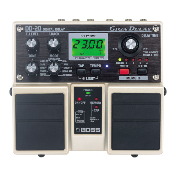
Page 16: Part Names And Functions
MEMORY Number Indicators (1–4) The indicator for the currently selected MEMORY number (1–4) lights. The indicator flashes while the DD-20 is in write standby; the indicator flashes more rapidly while the write operation is in progress. SELECT Button This changes MANUAL or memories 1–4. -
Page 17: Operating The Delay Time Knob
Operating the DELAY TIME Knob When adjusting the delay time with the DELAY TIME knob, the setting normally changes in units of one millisecond (or ten milliseconds if the time is ten seconds or longer). However, simultaneously pressing and turning the knob causes the delay time setting to change rapidly, allowing you to quickly reach the value you want, even with higher values. -
Page 18: Mode List
This simultaneously controls the delay sound's feedback level and vol- WARP ume to produce a totally unreal delay. This tone is modeled on the Roland “RE-201” Tape Echo. You can ad- just the settings to change the number of “heads.” TAPE * The delay time can be set in a range from 120 milliseconds to 23 seconds. - Page 19 DUAL Indicator (SHORT, LONG) Indicates the delay time as well as the delay (SHORT, LONG) when the DD-20 is set to DUAL mode. Output Mode Indicator (A:EFX, B:DIR, +4dB) “Setting the Output Mode” (p. 30) Control Pedal Function Indicator (ON/OFF, TAP, MEM) “Setting the External Pedal...
-
Page 20: Rear Panel
Part Names and Functions Rear Panel fig.26 INPUT Jacks (A (MONO), B) This is the input jack for connecting to the output of an electric guitar or other instrument or effects processor. For MONO use, make the connection to the A (MONO) jack. -
Page 21: How To Use Each Mode
How to Use Each Mode How to Use SOS (Sound On Sound) 1. Turn the MODE knob to “SOS.” 2. Press the ON/OFF pedal to start recording. Play what is to be used as the basic phrase. The remaining memory is indicated as a percentage in the display. fig.29 Blink 3. -
Page 22: How To Use Twist
How to Use Each Mode How to Use TWIST 1. Turn the MODE knob to “TWIST.” 2. Hold down the ON/OFF pedal. The delay sound starts to oscillate, then the oscillation speeds up as its pitch increases. fig.32 Blink 3. Release the pedal. The oscillating sound begins to fade away, and the normal delay sound returns. -
Page 23: How To Use Tape
How to Use TAPE You can have either one or two “playback heads” used for the tape echo effect. Setting this to “2” produces a multi-tap delay effect. 1. Turn the MODE knob to “TAPE.” 2. Hold down the ON/OFF pedal until “HEd1” or “HEd2” appears in the display. 3. -
Page 24: How To Use Dual
How to Use Each Mode How to Use DUAL Although DUAL mode features a short delay and long delay connected in series, you can change the delay time for the short delay. 1. Turn the MODE knob to “DUAL.” 2. Hold down the ON/OFF pedal until “SHORT” appears in the display. In this case, the short delay’s delay time is indicated. -
Page 25: How To Use Modulate
How to Use MODULATE You can change the MODULATE modulation rate and depth settings. 1. Turn the MODE knob to “MODULATE.” 2. Hold down the ON/OFF pedal until “r” appears in the display. The rate value appears next to the “r” in the display. fig.37 3. -
Page 26: How To Use The Tempo Function
How to Use the Tempo Function The DD-20 includes a “Tempo function,” which allows you to specify the delay time in terms of note lengths. The display is switched as shown below each time you press the TEMPO button. fig.39... -
Page 27: Indicating The Bpm In The Delay Time Display
Indicating the BPM in the Delay Time Display You can switch the DD-20’s time delay display to show the tempo (BPM). If, for example, you already know the BPM of the song you are performing, you can get a perfectly synchronized delay effect by setting the delay time with the indicated tempo (BPM). -
Page 28: Settings Made When The Power Is Switched On
Settings Made When the Power is Switched ON You can make the following settings with the operations performed while turning on the power. fig.42 WRITE Button Returns settings to their factory defaults. “Returning Settings to Their Factory Defaults” (p. 34) ON/OFF Pedal This sets the output mode. -
Page 29: Changing The Pedal Mode Settings
Changing the Pedal Mode Settings Use the following to change the Pedal mode settings. * Pedal mode settings are saved even after the power is turned off. 1. Switch off the power. 2. While holding down the SELECT button, switch on the power. The MEMORY 1–3 indicator corresponding to the current Pedal mode settings flashes. -
Page 30: Setting The Output Mode
Settings Made When the Power is Switched ON Setting the Output Mode When using the DD-20 while connected to a guitar or bass amp, mixer, or multitrack recorder SEND/RETURN, you can set the output level (+4 dB) and method of output from the OUTPUT jacks (A: Direct Sound/B: Effect Sound) to match the device connected to the DD-20. -
Page 31: Setting The External Pedal Function
Setting the External Pedal Function You can connect an optional foot switch (the FS-5U or FS-5L) to the CTL PEDAL jack and use the pedal for turning the effects on and off, for tap input, and for switching memories. fig.45 Polarity switch Connection cord (1/4 inch phone type) 1. - Page 32 DD-20’s CTL PEDAL jack and the OD-20’s AMP CTRL jack. • When using an external pedal to turn the effect on and off with the DD-20 set to CTL1 mode, if you try to switch the effect on or off with the DD-20’s ON/OFF pedal, the external pedal’s actual function will differ from the function that is...
-
Page 33: Changing How Memory Numbers Are Indicated
Select the pattern that provides the easiest way to check the memory in any particular environment. When using the DD-20 in dimly lit surroundings, you can confirm memory numbers more easily by using the Lighting Pattern 2 setting. -
Page 34: Returning Settings To Their Factory Defaults
Settings Made When the Power is Switched ON Returning Settings to Their Factory Defaults You can restore the following settings to their original factory values. Memory Settings MANUAL Delay Time (p. 9) (when the power is switched on) DUAL Short Delay Time (p. 24) MODULATE Rate/Depth (p. -
Page 35: Troubleshooting
Troubleshooting The power doesn’t come on. Is the guitar connected correctly to the INPUT A (MONO) jack? Check the connections again (p. 4–p. 7). * When running off batteries, the unit won’t switch on unless there’s something plugged into the INPUT jack. - Page 36 Troubleshooting Pressing the ON/OFF pedal does not switch on or off as intended. Is the Pedal mode set to SOS, WARP or TWIST? The pedal functions differently according to the Pedal mode settings. For more details, refer to the description of each mode. SOS (p.
-
Page 37: Sample Settings
Sample Settings SMOOTH (Memory 1) fig.36 Roland SPACE ECHO RE-201 (Memory 2) fig.36 MODE: TAPE HEd2 DUAL (Memory 3) fig.36 MODE: DUAL/SHORT 50 msec... - Page 38 Sample Settings MODULATE (Memory 4) fig.36 MODE: MODULATE/RATE 80, DEPTH 70 TWIST fig.36 Holding down the ON/OFF pedal produces the twist effect. REVERSE fig.36...
- Page 39 Sample Settings ROOM AMBIENCE fig.36 SLAP BACK ECHO fig.36 MODULATE DOUBLING fig.36 MODE: MODULATE/RATE 25, DEPTH 95...
-
Page 40: Setting Memo
Setting Memo fig.36 fig.36 fig.36... -
Page 41: Specifications
Specifications DD-20: DIGITAL DELAY Nominal Input Level -20 dBu (GUITAR/BASS) +4 dBu (AMPLIFIER SEND/RETURN) Input Impedance Nominal Output Level -20 dBu (GUITAR/BASS) +4 dBu (AMPLIFIER SEND/RETURN) Output Impedance 1 k (OUTPUT A (MONO), B) (PHONES) Recommended Load Impedance 10 k Residual Noise Level -93 dBu or less (IHF-A typ.) -
Page 42: Index
Index ... 18 ANALOG ... 3 Batteries ... 27 ... 4 Connection ... 31 CTL PEDAL ... 17 Delay time ... 17 DELAY TIME knob ... 25 Depth ... 30 Direct Sound ... 18, 24 DUAL ... 30 Effect Sound ... - Page 43 This product complies with the requirements of European Directive 89/336/EEC. FEDERAL COMMUNICATIONS COMMISSION RADIO FREQUENCY INTERFERENCE STATEMENT This equipment has been tested and found to comply with the limits for a Class B digital device, pursuant to Part 15 of the FCC Rules.
- Page 44 G6017366 ’03-2-FA1-11N...
Need help?
Do you have a question about the Giga Delay DD-20 and is the answer not in the manual?
Questions and answers