Table of Contents
Advertisement
Quick Links
MMWMP240
OWNER'S MANUAL
WARNING:
Tig welder is only for steel and the user cannot tig weld aluminum.
Read carefully and understand all ASSEMBLY AND OPERATION
INSTRUCTIONS before operating. Failure to follow the safety rules and other
basic safety precautions may result in serious personal injury.
WELDER WARRANTY
Advertisement
Table of Contents

Related Manuals for Cornwell Tools MMWMP240


Summary of Contents for Cornwell Tools MMWMP240
- Page 1 MMWMP240 OWNER’S MANUAL WARNING: Tig welder is only for steel and the user cannot tig weld aluminum. Read carefully and understand all ASSEMBLY AND OPERATION INSTRUCTIONS before operating. Failure to follow the safety rules and other basic safety precautions may result in serious personal injury.
-
Page 2: Limited Warranty
CORNWELL QUALITY TOOLS EFFECTIVE JANUARY 1, 2015 LIMITED WARRANTY This warranty applies to the original purchaser and is subject to the terms and conditions listed below. This Limited Warranty is for new equipment sold after the above date, providing coverage for defects in material and workmanship at the time it is shipped from the factory. -
Page 3: Important Safety Considerations
WARNING: Read and understand all instructions. Failure to follow all instructions listed below may result in serious injury. CAUTION: Do not allow persons to operate or assemble this unit until they have read this manual and have developed a thorough understanding of how this unit works. WARNING: The warnings, cautions, and instructions discussed in this instruction manual cannot cover all possible conditions or situations that could occur. - Page 4 material being welded, ground or electrode from another welder. -Do not weld if you are in an awkward position. Always have a secure stance while welding to prevent accidents. Wear a safety harness if working above ground. -Do not drape cables over or around your body. -Wear a full coverage helmet with appropriate shade (see ANSI Z87.1 safety standard) and safety glasses while welding.
- Page 5 -Always use a helmet that covers your full face from the neck to top of head and to the back of each ear. -Use a lens that meets ANSI standards and safety glasses. For welders under 160 Amps output, use a shade 10 lens; for above 160 Amps, use a shade 12. Refer to the ANSI standard Z87.1 for more information.
-
Page 6: Technical Specifications
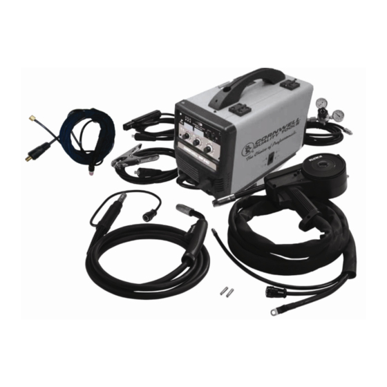
-Keep people with pacemakers away from your welding area when welding. -Do not wrap cable around your body while welding. -Wrap MIG gun and ground cable together whenever possible. -Keep MIG gun and ground cables on the same side of your body. Shielding Gas Cylinders Can Explode High pressure cylinders can explode if damaged, so treat them carefully. - Page 7 DESCRIPTION The Cornwell MP240 is a portable DC inverter wire feed welder capable of welding with solid wire (with shielding gas) or with flux core wire. This machine also has smooth DC Stick capabilities and the ability to perform lift start DC TIG welding on steel and stainless steel materials with the included TIG Torch.
- Page 8 POWER INDICATOR LIGHT In the “OFF” position no power is being supplied to the torch. In the “ON” position power is supplied to the main transformer and control circuit. PROTECTION INDICATOR LIGHT If the duty cycle of the welder is exceeded, the internal temperature will exceed safe temperatures and the machine will shut down.
-
Page 9: Mig Torch Assembly
ASSEMBLY 1. MIG TORCH ASSEMBLY 1.1 Locate the retaining bolt inside the front panel on the drive system. Loosen the retaining bolt. 1.2 Make note of the retaining groove on the back end of the MIG torch. Retaining Groove Retaining Bolt 1.3 Insert the back end of the MIG torch into the MIG socket on the front of your machine. - Page 10 Connect the ground cable to the Negative (-) weld output connection for MIG welding. If welding with self-shielded flux core, connect the ground cable to the Positive (+) weld output connection. When stick welding, the electrode holder is connected to the Positive (+) weld output connection.
- Page 11 2.3 We recommend removing the MIG torch when the Spool Gun is connected to avoid accidental arcing. Loosen the retaining bolt and slide the MIG torch out of the front of the machine. Disconnect the 5-Pin trigger connection on the front of the machine. 2.4 Carefully slide the gas connector and the weld power connection through the weld cable access opening in the front of the machine.
-
Page 12: Installation
3. DC STICK WELDING ASSEMBLY Be aware that the ELECTRODE HOLDER will be electrically HOT when the Input Power Switch on the welder is turned on. 3.1 Install the ground cable quick connector to the Negative (-) Weld Output Connector. 3.2 Secure the ground clamp to the work piece 3.3 Install the electrode cable quick connector to the Positive (+) Weld Output Connector. - Page 13 2. Drive Roll Installation Before installing any welding wire into the unit, the proper sized groove must be placed into position on the wire drive mechanism. Adjust the drive roller according to the following steps, see following picture about the wire feeder structure: 1.
- Page 14 2.3 Match the drive roller wire groove to the wire diameter, see the chart below. Wire Roller Diameter Groove .024 inch .030 inch .035 inch The drive roller has two wire size grooves in it. When installing the drive roller, the number stamped on the drive roller indicates the wire groove it is aligned with.
- Page 15 NOTE: • Before installing, make sure that you have removed any wire from the MIG gun assembly. This will help to prevent the possibility of the wire jamming inside the MIG gun liner. • Be careful when removing the welding nozzle. The contact tip on this welder is electrically live when the torch trigger is pulled.
- Page 16 3.7 Setting the wire spool tension. a) Turn the spool of wire with one hand. b) Increase the spool tension by tightening (turn clockwise) the wing nut while turning the spool. Turn the spool while tightening the wing nut until the spool slows down and you feel a slight drag. Stop tightening the wing nut, you may need to repeat these steps until proper spool tension is achieved.
- Page 17 3.23 Cut off excess wire that extends past the end of the nozzle more than 1/4 inch. 3.24 Turn the welder ON. 4. SETTING THE DRIVE ROLL TENSION Arc flash can injure eyes! To reduce the risk of arc flash, make certain that the wire •...
- Page 18 connection. Rotate the bottle so the gas connection is not pointing toward you or any other person. Turn the valve on the gas bottle clockwise and quickly close. This quick thrust of gas will clear any debris in the connection. Connect the regulator to the gas bottle connection. Use a wrench to snug up the connection.
-
Page 19: Mig Operation
MIG OPERATION High voltage danger from power source! Consult a qualified electrician for proper installation of receptacle at the power source. This welder must be grounded while in use to protect the operator from electrical shock. If you are not sure if your outlet is properly grounded, have it checked by a qualified electrician. - Page 20 6. DISTANCE FROM THE WORK PIECE - If the nozzle is held off the work piece, the distance between the nozzle and the work piece should be kept constant and should not exceed 1/4 inch or the arc may begin sputtering, signaling a loss in welding performance. 7.
- Page 21 ELECTRIC SHOCK CAN KILL! To prevent ELECTRIC SHOCK, do not perform any welding while standing, kneeling, or lying directly on the grounded work piece. 8.1 Moving the torch Torch travel refers to the movement of the torch along the weld joint and is broken into two elements: Direction and Speed.
- Page 22 8.3 Welding position FLAT POSITION is easiest of the welding positions and is most commonly used. It is best if you can weld in the flat position if at all possible as good results are easier to achieve. HORIZONTAL POSITION Is performed very much the same as the flat weld except that angle B (see HOLDING THE TORCH) is such that the wire, directed more toward the metal above the weld joint is to help prevent the weld puddle from running downward while still allowing slow enough travel speed.
- Page 23 falling into the nozzle. Angle B should be held at zero degrees so that the wire is aiming directly into the weld joint. If you experience excessive dripping of the weld puddle, select a lower heat setting. Also, the weave bead tends to work better than the stringer. 8.4 Multiple pass welding Butt Weld Joints When butt welding thicker materials, you will need to prepare the edges of the material to be joined by grinding a bevel on the edge of one or both pieces of the metal being joined.
- Page 24 8.5 Spot welding There are three methods of spot welding: Burn-Through, Punch and Fill, and Lap. Each has advantages and disadvantages depending on the specific application as well as personal preference. 1. The BURN-THROUGH METHOD welds two overlapped pieces of metal together by burning through the top piece and into the bottom piece.
- Page 25 8.6 SPOT WELDING INSTRUCTIONS 1. Select the wire diameter and heat setting recommended above for the method of spot welding you intend to use. 2. Tune in the wire speed as if you were going to make a continuous weld. 3.
-
Page 26: Ground Clamp Connection
2. GROUND CLAMP CONNECTION Clear any dirt, rust, scale, oil or paint on the ground clamp. Make certain you have a good solid ground connection. A poor connection at the ground clamp will waste power and heat. Make sure the ground clamp touches the metal. 3. - Page 27 4.1. When proper rod is used: 4.1.a. The bead will lay smoothly over the work without ragged edges 4.1.b. The base metal puddle will be as deep as the bead that rises above it 4.1.c. The welding operation will make a crackling sound similar to the sound of eggs frying 4.2.
- Page 28 6.2 Striking the arc EXPOSURE TO A WELDING ARC IS EXTREMELY HARMFUL TO THE EYES AND SKIN! Prolonged exposure to the welding arc can cause blindness and burns. Never strike an arc or begin welding until you are adequately protected. Wear flame-proof welding gloves, a heavy long sleeved shirt, trousers without cuffs, high topped shoes, and an ANSI approved welding helmet.
- Page 29 The weave bead Used when you want to deposit metal over a wider space than would be possible with a stringer bead. It is made by weaving from side to side while moving with the electrode. It is best to hesitate momentarily at each side before weaving back the other way. 6.4 Welding position Flat position It is easiest of the welding positions and is most commonly used.
- Page 30 accumulation of dirty metal scale on the finished weld. Slag should be removed by using a chipping hammer. PEENING THE SLAG FROM A WELD JOINT CUASES SMALL CHIPS OF METAL TO FLY THROUGH THE AIR! Metallic chips flying through the air can cause eye injury or injury to other parts of the head, hands or exposed portions of the body.
-
Page 31: Maintenance
8. Follow these steps for striking an arc while TIG welding. 8.1 Open the shielding gas valve on the torch handle to begin gas flow. 8.2 Rest the TIG torch nozzle on the work piece taking care to not touch the installed tungsten electrode. -
Page 32: Troubleshooting
TROUBLESHOOTING SYMPTOM POSSIBLE CAUSE CORRECTIVE ACTION Unit Does Not Power Up Unit Is Not Plugged In Plug In Unit Input Power Circuit Breaker Not On Reset Input Power Circuit Breaker The Main Power Switch Is Not Replace Main Power Switch Working Protection Indicator Is On The internal temperature is too high. - Page 33 MAIN CIRCUIT CHART -15V +15V Page of 36...
-
Page 34: Diagram & Parts List
DIAGRAM & PARTS LIST Page of 36... - Page 35 Reference # Description Part Number Qty. Enclosure 1.1.01.01.0399 Handle 2.05.08.115 Plastic hinge 2.05.17.012 Control board 1.1.05.02.0208 PCB support plate 1.1.01.05.2848 Cable sleeve 2.20.05.416 1.1.02.01.8701 Vertical board Right panel 1.1.01.02.8679 Wire feeder lock 2.08.07.803 Wire spool base cap 2.05.05.306 Wire spool bolt 2.05.05.308 Spool shaft spring 2.06.29.037...
- Page 36 Distributed by CORNWELL QUALITY TOOLS 667 SEVILLE RD WADSWORTH OH 44281 www.conwelltools.com Made in China Page of 36...
Need help?
Do you have a question about the MMWMP240 and is the answer not in the manual?
Questions and answers