Table of Contents

Related Manuals for Cornwell Tools MMW240TIG


Summary of Contents for Cornwell Tools MMW240TIG
- Page 1 MMW240TIG OWNER’S MANUAL WARNING: Read carefully and understand all ASSEMBLY AND OPERATION INSTRUCTIONS before operating. Failure to follow the safety rules and other basic safety precautions may result in serious personal injury. 2/2016...
- Page 2 Effective December 22, 2015 LIMITED WARRANTY FOR MMW240TIG This warranty applies to the original purchaser and is subject to the terms and conditions listed below. This Limited Warranty is for new equipment sold after the above date, providing coverage for defects in material and workmanship at the time it is shipped from the factory.
-
Page 3: General Safety Rules
WARNING: Read and understand all instructions. Failure to follow all instructions listed below may result in serious injury. CAUTION: Do not allow persons to operate or assemble this MMW240TIG until they have read this manual and have developed a thorough understanding of how the MMW240TIG works. - Page 4 -Connect ground lead as close to the area being welded as possible to ensure a good ground. -Do not allow any body part to come in contact with the torch if you are in contact with the material being welded, ground or electrode from another welder. -Do not weld if you are in an awkward position.
- Page 5 UV and IR Arc Rays The welding arc produces ultraviolet (UV) and infrared (IR) rays that can cause injury to your eyes and skin. Do not look at the welding arc without proper eye protection. -Always use a helmet that covers your full face from the neck to top of head and to the back of each ear.
- Page 6 Electromagnetic Field -Electromagnetic fields can interfere with various electrical and electronic devices such as pacemakers. -Consult your doctor before using any electric arc welder or cutting device -Keep people with pacemakers away from your welding area when welding. -Do not wrap cable around your body while welding. -Wrap torch and ground cable together whenever possible.
-
Page 7: Technical Specifications
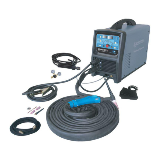
Electrode Holder with cable. The MMW240TIG is the ideal Stick and TIG welder for every shop. The DC stick mode allows you to stick weld when your application requires it. In the DC TIG mode you are able to TIG weld metals such as steel and stainless steel. -
Page 8: Know Your Welder
KNOW YOUR WELDER Front Panel Controls Electrode Holder And Cable Inert Gas Regulator/Flowguage Ground Clamp And Cable Foot TIG Torch Pedal Accessories Inert Gas Hose Style 17 TIG Torch FRONT PANEL CONTROLS See the next section for a complete description of the front panel controls. INERT GAS REGULATOR/FLOWGAUGE Installs directly on the shielding gas cylinder. -
Page 9: Front Panel Controls
FRONT PANEL CONTROLS Mode Digital Amperage Digital Function Function Control Selector Display Control Display Display Indicators Operation Indicator Lights Advanced Settings Contactor Control (See Next Section) Selector Gas Purge Button Process Selector Functional Control Functional Control Functional Indexing Increase Button Indexing Decrease Button Control MODE SELECTOR... -
Page 10: Advanced Settings
ALARM INDICATOR LIGHT The Alarm Indicator Light will be illuminated when the input voltage is either too high or too low. CONTACTOR CONTROL SELECTOR Push the Contactor Control Selector button to choose Remote Amp when you are using a foot pedal for remote amperage control. - Page 11 HOT START INDICATOR LIGHT In the stick mode only, use one of the FUNCTIONAL CONTROL INDEX BUTTONS to turn on the HOT START indicator light. The functional control knob can then be used to increase or decrease the hot start amperage setting as indicated on the Digital Amperage Display. Hot Start that is increased will generally result in better arc starting on hard to start electrodes.
- Page 12 knob can then be used to increase or decrease the pulse frequency setting. The functional control display indicator light HZ will be on indicating the set value in the Digital Functional Control Display. Pulse frequency can be used in the pulse mode using the remote foot pedal or when performing a sequenced weld.
-
Page 13: Installation
balance can be used in the pulse mode using the remote foot pedal or when performing a sequenced weld. Increase AC balance when the material you are welding has a higher amount of oxidation and more cleaning is needed during the weld. Be mindful that increasing the AC balance will also create a wider arc with shallower penetration. -
Page 14: Back Panel Connections
4. TIG WELDING CONNECTION – DC TIG welding is generally performed DC Electrode negative. That means that the TIG torch and cable would be attached to the Negative (-) weld output connection and the ground cable and clamp would be attached to the Positive (+) weld output connection. -
Page 15: Remote Control Installation
Always secure cylinder upright to a cart or stationary object. Keep cylinders away from welding or electrical circuits. Use the proper regulators, gas hose and fittings for the specific application. 7.1. Connect one end of the gas hose to the gas hose connection on the back of the welder. Use a wrench to snug up the connection. - Page 16 8.1.b – Sequencer Control – Use the push button control in the TIG mode when using the sequencer. Push the push button to initiate the arc and then push it again to advance to the next step in the sequencer. Push Button Connection 8.2 Remote Contactor And Amperage Control –...
-
Page 17: Pre Operation Set-Up
PRE OPERATION SET-UP Mode Digital Amperage Digital Function Function Control Selector Display Control Display Display Indicators Operation Indicator Lights Advanced Settings Contactor Control (See Next Section) Selector Gas Purge Button Process Selector Functional Control Functional Control Functional Indexing Increase Button Indexing Decrease Button Control 1. - Page 18 2. SET UP INSTRUCTIONS FOR DC TIG WELDING Connect TIG torch to the NEGATIVE terminal on the front of the machine (See item 4 of the INSTALLATION section). Connect the ground cable to the POSTIVE terminal on the front of the machine (See item 4 of the INSTALLATION section).
- Page 19 Use the PROCESS SELECTOR BUTTON to Select HF TIG on front panel Use the MODE SELECTOR BUTTON on the front panel to Select AC. Use the CONTACTOR CONTROL BUTTON TO Select RMT AMP position on front panel. ...
- Page 20 PULSE TIG SET-UP 1. Follow the TIG welding set-up in the previous section. 2. For Manual Pulse TIG, using a foot pedal, set the CONTACTOR CONTROL SELECTOR so that the RMT AMP light is on. See the next section for sequencer set-up. 3.
- Page 21 indicator light is on. Use the FUNCTIONAL CONTROL KNOB to select the preferred Pulse Frequency as displayed on the Digital Function Control Display. Example: Set Pulse Frequency to 1. The Pulse Frequency is the number of times per second that the machine changes from Peak Current to Back Ground Current.
- Page 22 NOTE: Using a sequencer will be more successful for DC TIG applications. Amperage controls are limited to set values in the sequencer. AC TIG applications usually require more amperage flexibility. 2. Follow the Pulse TIG set-up in the previous section if you decide to use pulse TIG in conjunction with the sequencer.
-
Page 23: Setting Up The Work Piece
BASIC STICK WELDING OPERATION High voltage danger from power source! Consult a qualified electrician for proper installation of receptacle at the power source. This welder must be grounded while in use to protect the operator from electrical shock. If you are not sure if your outlet is properly grounded, have it checked by a qualified electrician. -
Page 24: Ground Clamp Connection
2. GROUND CLAMP CONNECTION Clear any dirt, rust, scale, oil or paint on the ground clamp. Make certain you have a good solid ground connection. A poor connection at the ground clamp will waste power and heat. Make sure the ground clamp touches the metal. 3. -
Page 25: Welding Techniques
4.2. b. The arc will be difficult to maintain 4.3. When the rod is too large 4.3. a. The arc will burn through light metals 4.3. b. The bead will undercut the work 4.3. c. The bead will be flat and porous 4.3. - Page 26 It is important that the gap be maintained during the welding process and it should be neither too wide nor too narrow. If too narrow, the rod will stick to the work piece. If too wide, the arc will be extinguished.
- Page 27 The horizontal position it is performed very much the same as the flat weld except that the angle is different such that the electrode, and therefore the arc force, is directed more toward the metal above the weld joint. This more direct angle helps prevent the weld puddle from running downward while still allowing slow enough travel speed to achieve good penetration.
- Page 28 BASIC TIG WELDING OPERATION High voltage danger from power source! Consult a qualified electrician for proper installation of receptacle at the power source. This welder must be grounded while in use to protect the operator from electrical shock. If you are not sure if your outlet is properly grounded, have it checked by a qualified electrician.
- Page 29 Tungsten Electrode T ypes Page of 35...
- Page 30 Aluminum W elding Material W elding Rate TIG W elding is g enerally regarded as a sp ecializ ed p rocess tha t requires operato r competenc y. W hile many of the p rinciples outlined in th e pre vious Arc W elding section a re a pplicable a comprehensive outline of the TIG W elding process is outside th e scope of this Ope ra ting Manual .
-
Page 31: Troubleshooting
TROUBLESHOOTING SYMPTOM POSSIBLE CAUSE CORRECTIVE ACTION Unit Does Not Power Up Unit Is Not Plugged In Plug In Unit Input Power Circuit Breaker Not On Reset Input Power Circuit Breaker The Main Power Switch Is Not Working Replace Main Power Switch Leave power on and let the fan cool the unit. -
Page 32: Diagram & Parts List
DIAGRAM & PARTS LIST REF # PART # DESCRIPTION 105500015 HANDLE 155500001 ENCLOSURE 105500016 REMOTE CONTROL MODULE 105500017 CONTROL PC BOARD 105500018 INPUT POWER STRAIN RELIEF 105500019 INPUT POWER CABLE HOLDER 105500020 INPUT POWER CABLE HOLDER 105500021 INPUT POWER SWITCH 155500002 BACK PANEL 105500023... - Page 33 FRONT PLASTIC PANEL 105500040 TIG TORCH 105500041 GROUND CABLE AND CLAMP 105200136 QUICK CONNECT SOCKET 105500042 FUNCTIONAL CONTROL KNOB 155500003 CORNWELL MMW240TIG FACEPLATE 105500043 FACEPLATE SUPPORT PC BOARD 105500044 HALL DEVICE 105500045 RECTIFIER LOWER HEATSINK 105500046 DIODE 105500047 RECTIFIER UPPER HEATSINK...
- Page 34 Reference # Part# Description Qty. 105500055 TORCH HANDLE 105500056 TORCH HEAD 105500006 SHORT BACK CAP 105500005 LONG BACK CAP 105500011 COLLET 1/16 IN. 105500057 COLLET 5/64 IN. 105500058 COLLET 3/32 IN. 105500008 COLLET BODY 105500013 NOZZLE #5 105500014 NOZZLE#6 105500059 NOZZLE#7 105500060 QUICK CONNECTOR MALE...
- Page 35 Distributed by CORNWELL QUALITY TOOLS 667 SEVILLE RD WADSWORTH OH 44281 www.conwelltools.com Made in China Page of 35...
Need help?
Do you have a question about the MMW240TIG and is the answer not in the manual?
Questions and answers