Table of Contents

Related Manuals for Cornwell Tools MMWMP242DVI


Summary of Contents for Cornwell Tools MMWMP242DVI
- Page 1 MMWMP242DVI OWNER’S MANUAL 3/2019 WARNING: Read carefully and understand all ASSEMBLY AND OPERATION INSTRUCTIONS before operating. Failure to follow the safety rules and other basic safety precautions may result in serious personal injury.
-
Page 2: Limited Warranty
EFFECTIVE AUGUST 7, 2015 LIMITED WARRANTY This warranty applies to the original purchaser and is subject to the terms and conditions listed below. This Limited Warranty is for new equipment sold after the above date, providing coverage for defects in material and workmanship at the time it is shipped from the factory. -
Page 3: General Safety Rules
WARNING: Read and understand all instructions. Failure to follow all instructions listed below may result in serious injury. CAUTION: Do not allow persons to operate or assemble this MMWMP242DVI until they have read this manual and have developed a thorough understanding of how the MMWMP242DVI works. - Page 4 Always replace or repair damaged components before using the welder. -Check all components to ensure they are clean and in good operating condition before use. 1.3 Use of Your Welder Do not operate the welder if the output cable, electrode, torch, wire or wire feed system is wet. Do not immerse them in water.
- Page 5 environment where you will be working. -Do not weld on coated materials (galvanized, cadmium plated or containing zinc, mercury or barium). They will emit harmful fumes that are dangerous to breathe. If necessary, use a ventilator, respirator with air supply or remove the coating from the material in the weld area. -The fumes emitted from some metals when heated are extremely toxic.
- Page 6 -Do not put hands or fingers near moving parts such as drive rolls of fan MMWMP242DVI USE AND CARE • Do not modify this unit in any way. Unauthorized modification may impair the function and/or safety and could affect the life of the equipment.
-
Page 7: Technical Specifications
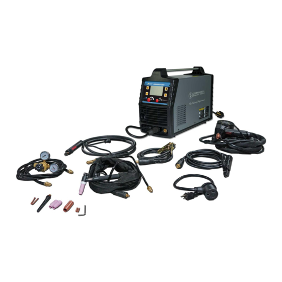
35 lbs. DESCRIPTION The Cornwell MMWMP242DVI is an inverter-powered, dual voltage, wire feed welder for flux core and MIG welding plus a DC stick welder. It features a Synergic LCD control that allows the operator to select process and weld settings. It comes complete with a regulator and gas hose for easy connection for MIG welding plus a weld cable and electrode holder for DC stick welding. - Page 8 Welding Voltage Control LCD Screen Multi-Function Adjustment/Selector Spool Gun Knob (MMWEZFSG2) MIG Torch and Consumables Inert Gas Regulator Inert Gas Hose Electrode Holder and Cable Ground Cable TIG Torch and 120V Adapter and Clamp Consumables Cord (MMWACTT2V) LCD SYNERGIC CONTROL The LCD Synergic Control sets and operates the welder based on selections the operator makes in weld process and material selections.
-
Page 9: Installation
POWER CORD AND PLUG Plug this unit into a 230V, 50-amp circuit breaker power supply when operating on 230V. If running on 120V power using the supplied 120V power cord adapter, plug this unit into a 120V, 20-amp circuit breaker power supply. INERT GAS REGULATOR AND HOSE The Inert Gas Regulator installs on the shielding gas cylinder for MIG welding with solid wires. - Page 10 4. INSTALL THE WIRE ROLLER - The wire roller has been factory installed. However, check to make certain the correct wire groove is in place to accommodate the size of wire you are using. Open the wire feed compartment. Adjust the drive roller according to the following steps. See Figure 2 about the wire feeder structure: Figure 2 Open the door to the welder drive compartment.
- Page 11 NOTE: Be very careful when removing the welding nozzle. The contact tip on this welder is live whenever the torch trigger is pulled. Make certain power is turned OFF. 5. INSTALL THE WIRE - We recommend the usage of .023, .030 & .035 MIG wire, or .030 and .035 flux core wire, on this unit.
- Page 12 Figure 4 5.2.5 The welder can use either 4 inch or 8 inch spools. See Figure 5 for additional reference. The wing nut controls the tension on the spool. 4 Inch 8 Inch Figure 5 5.2.6 Setting the wire spool tension. a) Turn the spool of wire with one hand. b) Increase the spool tension by tightening (turn clockwise) the wing nut while turning the spool.
- Page 13 5.2.9 Cut off any bent portion of the wire using a wire cutter. 5.2.10 Loosen the tension adjusting knob holding the drive tension arm in place and lift the tension arm up off the drive roller. 5.2.11 Insert the wire into the inlet guide tube and feed it across the drive roller and into the torch assembly about six inches.
-
Page 14: Gas Installation
6. SETTING THE DRIVE ROLL TENSION • Arc flash can injure eyes! To reduce the risk of arc flash, make certain that the wire coming out of the end of the torch does not come in contact with the work piece, ground clamp, or any grounded material during the drive tension setting process or arcing will occur. - Page 15 Reference Subassembly Gas Bottle Valve Gas Flow Gauge (Set at 20 CFH) Gas Pressure Gauge Regulator Gas Flow Adjuster Gas Hose Connection Gas Cylinder Figure 6 7.1.4 Connect the other end of the gas hose to the gas hose connection on the supplied regulator/flow gauge.
-
Page 16: Mig Torch Assembly
7.1.8 Gas Selection Different materials require different shielding gases when MIG welding. (Refer to the set-up chart inside the wire feed compartment.) Mild Steel: Use 75% Argon and 25% CO2 for reduced spatter and reduced penetration for thinner materials. DO NOT USE Argon gas concentrations higher than 75% on steel. - Page 17 3. Insert the back end of the MIG torch into the MIG socket on the front of your machine (Figure 8). Make certain to completely slide the torch all the way in. Slightly twist to assist with pushing the torch to the back of the receptacle. The retaining bolt can then be tightened, making certain the bolt sets down into the retaining groove on the back of the MIG torch.
- Page 18 Weld Cable Access Opening Figure 10 Open the wire compartment door. Connect the gas connection quick connector to the gas connector (1) on the back panel of the wire compartment. Connect the weld power connection to the bolt on the top of the MIG connector (2). Connect the 5-Pin trigger connector to the 5-Pin receptacle on the front of the machine (3).
-
Page 19: Understanding The Front Panel
OPERATING INSTRUCTIONS • High voltage danger from power source! Consult a qualified electrician for proper installation of receptacle. This welder must be grounded while in use to protect the operator from electrical shock. • Do not remove grounding prong or alter the plug in any way. Use only the supplied adapter between the plasma cutter's power cord and the power source receptacle. -
Page 20: Software Version
1.4.3 Turn the MULTI-FUNCTION ADJUSTMENT/SELECTION KNOB to desired language. 1.4.5 Press the MULTI-FUNCTION ADJUSTMENT/SELECTION KNOB to confirm your selection. 1.5 UNIT 1.5.1 Turn the MULTI-FUNCTION ADJUSTMENT/SELECTION KNOB until UNITS screen is displayed. 1.5.2 Push in the MULTI-FUNCTION ADJUSTMENT/SELECTION KNOB. The selected unit measurement is highlighted. - Page 21 to confirm your selection. 2.2.1.3 Use the MULTI-FUNCTION ADJUSTMENT/SELECTION KNOB to select your wire diameter. Press the MULTI-FUNCTION ADJUSTMENT/SELECTION KNOB to confirm your selection. 2.2.1.4 Use the MULTI-FUNCTION ADJUSTMENT/SELECTION KNOB to select the thickness of material to be welded. Press the MULTI-FUNCTION ADJUSTMENT/SELECTION KNOB to confirm your selection.
- Page 22 2.2.3.1 Use the MULTI-FUNCTION ADJUSTMENT/SELECTION KNOB to select if you are using a spool gun. Press the MULTI-FUNCTION ADJUSTMENT/SELECTION KNOB to confirm your selection. 2.2.3.1.1 No Spool Gun Used: 2.2.3.1.1.1 Connect the Weld Power Cable (See Figure 8 or follow the onscreen visual) to the Positive (+) Weld Output Connection.
- Page 23 2.2.3.1.2.2 Connect the Weld Power Cable (See Figure 8 or follow the onscreen visual) to the Positive (+) Weld Output Connection. Press the MULTI-FUNCTION ADJUSTMENT/SELECTION KNOB to confirm your selection. 2.2.3.1.2.3 Use the MULTI-FUNCTION ADJUSTMENT/SELECTION KNOB to select the thickness of wire you are using. Press the MULTI-FUNCTION ADJUSTMENT/SELECTION KNOB to confirm your selection.
- Page 24 your selection. 2.2.4.4 This machine is now set to weld. 2.2.4.4.1 Use the MULTI-FUNCTION ADJUSTMENT/SELECTION KNOB to fine tune wire feed speed. 2.2.4.4.2 Use the VOLTAGE CONTROL KNOB to fine turn voltage. 2.2.4.5 You can adjust other parameters: 2.2.4.5.1 Press the MULTI-FUNCTION ADJUSTMENT/SELECTION KNOB.
-
Page 25: Memory Load
ADJUSTMENT/SELECTION KNOB again to confirm. 2.2.6.1.6 Press the START/HOME BUTTON to exit. 2.2.7 Recalling A MIG Program 2.2.7.1 Go through the MIG welding set up steps above. 2.2.7.2 You can now recall previous parameters saved. 2.2.7.2.1 Press the MULTI-FUNCTION ADJUSTMENT/SELECTION KNOB to deselect the wire speed feed parameter adjustments 2.2.7.2.2 Turn the MULTI-FUNCTION ADJUSTMENT/SELECTION KNOB until you get to... -
Page 26: Arc Force
START. Push in the MULTI-FUNCTION ADJUSTMENT/SELECTION KNOB to confirm your selection. ARC FORCE 3.8.1 Press the MULTI-FUNCTION ADJUSTMENT/SELECTION KNOB to exit the Amperage Adjustment Mode. 3.8.2 Turn the MULTI-FUNCTION ADJUSTMENT/SELECTION KNOB to ARC FORCE. Press to confirm. 3.8.3 Turn the MULTI-FUNCTION ADJUSTMENT/SELECTION KNOB to adjust the ARC FORCE. -
Page 27: Mig Operation
MIG OPERATION • High voltage danger from power source! Consult a qualified electrician for proper installation of receptacle. This welder must be grounded while in use to protect the operator from electrical shock. • Do not remove grounding prong or alter the plug in any way. Use only the supplied adapter between the plasma cutter's power cord and the power source receptacle. -
Page 28: Welding Techniques
Connect the Ground Clamp to a scrap piece of the same type of material which you will be welding. It should be equal to or greater than the thickness of the actual work piece, and free of oil, paint, rust, etc. Select a heat setting. - Page 29 For most welding jobs you will pull the torch along the weld joint to take advantage of the greater weld puddle visibility. Travel speed is the rate at which the torch is being pushed or pulled along the weld joint. For a fixed heat setting, the faster the travel speed, the lower the penetration and the lower and narrower the finished weld bead.
- Page 30 The HORIZONTAL POSITION is performed very similarly to the flat weld except that angle B (see HOLDING THE TORCH) is such that the wire, directed more toward the metal above the weld joint, is to help prevent the weld puddle from running downward while still allowing slow enough travel speed.
- Page 31 Laying more than one bead into the same weld joint is known as a multiple-pass weld. The illustrations in the following figure show the sequence for laying multiple pass beads into a single “V” butt joint. NOTE: WHEN USING SELF-SHIELDING FLUX-CORE WIRE it is very important to thoroughly chip and brush the slag off each completed weld bead before making another pass or the next pass will be of poor quality.
-
Page 32: Spot Welding Instructions
4.5.1 The BURN-THROUGH METHOD welds two overlapped pieces of metal together by burning through the top piece and into the bottom piece. With the burn-through method, larger wire diameters tend to work better than smaller diameters. Wire diameters that tend to work best, with the burn-through method are 0.035 inch self-shielding flux-core wire. -
Page 33: Setting Up The Work Piece
sure the POWER switch is OFF when connecting your welder’s power cord directly to a properly grounded 230 VAC, 60 HZ, Single Phase, 50 Amp input power supply. Or, when using the supplied 120V adapter, connect the 120V Adapter to a properly grounded 120V, 20 Amp input power supply. -
Page 34: Ground Clamp Connection
2. GROUND CLAMP CONNECTION Clear any dirt, rust, scale, oil, or paint on the ground clamp. Make certain you have a good solid ground connection. A poor connection at the ground clamp will waste power and heat. Make sure the ground clamp touches the metal. 3. - Page 35 4.2.2 The arc will be difficult to maintain. When the rod is too large: 4.3.1 The arc will burn through light metals. 4.3.2 The bead will undercut the work. 4.3.3 The bead will be flat and porous. 4.3.4 The rod may be freeze or stick to the work piece. Note: The rate of travel over the work also affects the weld.
- Page 36 It is important that the gap be maintained during the welding process and it shouldn’t be too wide or too narrow. If it’s too narrow, the rod will stick to the work piece. If it’s too wide, the arc will be extinguished. It needs much practice to maintain the gap. Beginners may get sticker or arc extinguishing.
- Page 37 Welding position Flat position is the easiest of the welding positions and is most commonly used. It is best if you can weld in the flat position if at all possible, as good results are easier to achieve. Horizontal Position Flat Position The horizontal position is performed very much the same as the flat weld except that the angle is different such that the electrode, and therefore the arc force, is directed...
- Page 38 PEENING THE SLAG FROM A WELD JOINT CAUSES SMALL CHIPS OF METAL TO FLY THROUGH THE AIR! Metallic chips flying through the air can cause eye injury or injury to other parts of the head, hands or exposed portions of the body. Wear goggles or safety glasses with side shields and protect the hands and other exposed parts of the body with protective garments, or if possible, work with a shield between the body and the work piece.
-
Page 39: Maintenance
CFH. Then open the shielding gas valve on the torch to start the flow of shielding gas. 8. Follow these steps for striking an arc while TIG welding. Open the shielding gas valve on the torch handle to begin gas flow. Rest the TIG torch nozzle on the work piece taking care to not touch the installed tungsten electrode. -
Page 40: Troubleshooting
TROUBLESHOOTING Symptom Possible Cause Corrective Action Unit is not plugged in. Plug in unit. Unit does not Power Up. Input power circuit breaker not on. Reset input power circuit breaker. The main power switch is not working. Replace main power switch. Leave power on and let the fan cool the Protection The internal temperature is too high. - Page 41 Symptom Possible Cause Corrective Action Torch liner is plugged. Clear or replace torch liner. Connect shielding gas supply and turn No shielding gas. shielding gas on. Remove and reconnect the MIG torch to MIG torch is not correctly installed and make certain it is completely installed into shielding gas is not transferring to the arc.
-
Page 42: Diagram & Parts List
DIAGRAM & PARTS LIST Page of 44... - Page 43 REFERENCE # PART # DESCRIPTION 105200228 Handle 105200047 Gas Valve 105200211 Power Cable 105400050 Power Switch 105500091 Plastic back panel 155200069 Back panel 125400016 Power Cord Holder 165200042 Control PCB board 165200040 165200041 Mainboard 105200234 PC Board Support 155200065 Bottom Panel 105500033 Feet 155200070...
- Page 44 Distributed by CORNWELL QUALITY TOOLS 667 SEVILLE RD WADSWORTH OH 44281 www.cornwelltools.com Made in China Page of 44...
Need help?
Do you have a question about the MMWMP242DVI and is the answer not in the manual?
Questions and answers
Spool gun does not work properly