Table of Contents

Subscribe to Our Youtube Channel
Related Manuals for Cornwell Tools MMWMGS250


Summary of Contents for Cornwell Tools MMWMGS250
- Page 1 MMWMP251I OWNER’S MANUAL 3/2019 WARNING: Read carefully and understand all ASSEMBLY AND OPERATION INSTRUCTIONS before operating. Failure to follow the safety rules and other basic safety precautions may result in serious personal injury.
-
Page 2: Limited Warranty
EFFECTIVE AUGUST 7, 2015 LIMITED WARRANTY This warranty applies to the original purchaser and is subject to the terms and conditions listed below. This Limited Warranty is for new equipment sold after the above date, providing coverage for defects in material and workmanship at the time it is shipped from the factory. -
Page 3: General Safety Rules
WARNING: Read and understand all instructions. Failure to follow all instructions listed below may result in serious injury. CAUTION: Do not allow persons to operate or assemble this MMWMGS250 until they have read this manual and have developed a thorough understanding of how the MIG/Stick 220Si works. - Page 4 -Check all components to ensure they are clean and in good operating condition before use. 1.3 Use of Your Welder Do not operate the welder if the output cable, electrode, torch, wire or wire feed system is wet. Do not immerse them in water. These components and the welder must be completely dry before attempting to use them.
- Page 5 respirator with air supply or remove the coating from the material in the weld area. -The fumes emitted from some metals when heated are extremely toxic. Refer to the material safety data sheet for the manufacturer’s instructions. -Do not weld near materials that will emit toxic fumes when heated. Vapors from cleaners, sprays and degreasers can be highly toxic when heated.
-
Page 6: Technical Specifications
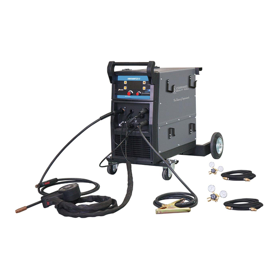
Electromagnetic Field -Electromagnetic fields can interfere with various electrical and electronic devices such as pacemakers. -Consult your doctor before using any electric arc welder or cutting device -Keep people with pacemakers away from your welding area when welding. -Do not wrap cable around your body while welding. -Wrap MIG gun and ground cable together whenever possible. - Page 7 DESCRIPTION The Cornwell MMWMP251I is an inverter-powered, wire feed welder for flux core and MIG welding plus a DC stick welder. It features a Synergic LCD control that allows the operator to select process and weld settings. It comes complete with two regulator’s and gas hoses for easy connection for MIG welding plus a weld cable and electrode holder for DC stick welding.
-
Page 8: Mig Torch
MIG TORCH The welding wire is driven through the welding cable and torch to the work piece. It is attached to the drive system. The trigger activates the drive motor. POWER CORD AND PLUG Plug this unit into a 230V, 50 amp circuit breaker power supply when operating on 230V. INERT GAS REGULATOR’S AND GAS HOSES The Inert Gas Regulator installs on the shielding gas cylinder for MIG welding with solid wires. - Page 9 3. INSTALL THE WIRE ROLLER - The wire roller has been factory installed. However, check to make certain the correct wire groove is in place to accommodate the size of wire you are using. Open the wire feed compartment. Adjust the drive roller according to the following steps, see following picture about the wire feeder structure: 3.1 Open the door to the welder drive compartment.
- Page 10 NOTE: - Burn through can occur if you attempt to weld mild or stainless steel thinner than 24 gauge. - Remove all rusted wire from your wire spool. If the whole spool is rusty, discard it. 4.2 Installing the wire Electrical Shock •...
- Page 11 4.2.5 The welder can use either 8 inch or 11 inch spools. The wire spool retainer secures the spool of wire onto the spool hub. The Wire Spool Tension Set Screw controls the tension on the spool. Wire Spool Tension Set Screw Wire Spool Retainer 4.2.6...
-
Page 12: Gas Installation
-The welding wire is electrically hot when the power is on and the torch trigger is activated. 4.2.16 Set the WIRE SPEED control to the middle of the wire speed range. 4.2.17 Straighten the MIG torch cable and pull the trigger in the gun handle to feed the wire through the torch assembly. - Page 13 NOTE: -There are two separate gas connections on the back of this unit. If connecting the shielding gas for the standard MIG torch, use the gas connection for the MIG torch on the back of the unit. If connecting the shielding gas for the Spool Gun, use the gas connection for the Spool Gun on the back of the unit.
-
Page 14: Mig Torch Assembly
6.7. Gas selection Different materials require different shielding gas when MIG welding, refer to the set up chart inside the wire feed compartment. Mild steel: Use 75% Argon and 25% CO2 for reduced spatter and reduced penetration for thinner materials. Do NOT USE Argon gas concentrations higher than 75% on steel. The result will be extremely poor penetration, porosity, and brittleness of weld. - Page 15 2. SPOOL GUN ASSEMBLY 2.1 This unit is set-up to accept the MMWEZFSG2 gun only. 2.2 The MMWEZFSG2 has three connection points at the back of the spool gun. (1) The gas connection is a slide on quick connector. (2) The weld power connection has a round ring connection.
- Page 16 3. DC STICK WELDING ASSEMBLY - Be aware that the ELECTRODE HOLDER will be electrically HOT when the Input Power Switch on the welder is turned ON. Install the ground cable quick connector to the negative (-) Weld Output Connector (Figure 8). Secure the ground clamp to the work piece.
-
Page 17: Understanding The Front Panel
UNDERSTANDING THE FRONT PANEL Reference Description Home/Start Button Previous Screen Button Voltage Control Knob Multi-Function Adjustment/Selection Knob Wire Job Button Gas Purge Button LCD Display 1. GENERAL SYSTEM SET-UP Press the START BUTTON Turn the MULTI-FUNCTION ADJUSTMENT/SELECTION KNOB to the SETTING selection Push in the MULTI-FUNCTION ADJUSTMENT/SELECTION KNOB. - Page 18 BRIGHTNESS 1.6.1 Turn the MULTI-FUNCTION ADJUSTMENT/SELECTION KNOB until BRIGHTNESS screen is displayed. 1.6.2 Push in the MULTI-FUNCTION ADJUSTMENT/SELECTION KNOB. 1.6.3 To change selection, Turn the MULTI-FUNCTION ADJUSTMENT/SELECTION KNOB to selected desired screen brightness. 1.6.4 Push in the MULTI-FUNCTION ADJUSTMENT/SELECTION KNOB to confirm your selection.
- Page 19 2.2.1.6 You can adjust other parameters: 2.2.1.6.1 Press the MULTI-FUNCTION ADJUSTMENT/SELECTION KNOB. Wire Speed will no longer be highlighted, but will have a box around it. Turn the MULTI-FUNCTION ADJUSTMENT/SELECTION KNOB to go through other options. Press the MULTI-FUNCTION ADJUSTMENT/SELECTION KNOB to adjust the highlighted Option.
- Page 20 MULTI-FUNCTION ADJUSTMENT/SELECTION KNOB to confirm your selection. (.040 or .045 are ran the same). Only .045 wire diameter is recommended when not using a spool gun. To run other wire sizes of aluminum wire without a spool gun, use the MIG MANUAL setup.
- Page 21 2.2.3.1.2.4 Use the MULTI-FUNCTION ADJUSTMENT/SELECTION KNOB to select the thickness of material to be welded. Press the MULTI-FUNCTION ADJUSTMENT/SELECTION KNOB to confirm your selection. 2.2.3.1.2.5 This machine is now set to weld. 2.2.3.1.2.5.1 Use the MULTI-FUNCTION ADJUSTMENT/SELECTION KNOB to fine tune wire feed speed. 2.2.3.1.2.5.2 Use the VOLTAGE CONTROL KNOB to fine turn voltage.
- Page 22 2.2.4.5 You can adjust other parameters: 2.2.4.5.1 Press the MULTI-FUNCTION ADJUSTMENT/SELECTION KNOB. Wire Speed will no longer be highlighted, but will have a box around it. Turn the MULTI-FUNCTION ADJUSTMENT/SELECTION KNOB to go through other options. Press the MULTI-FUNCTION ADJUSTMENT/SELECTION KNOB to adjust the highlighted Option.
- Page 23 2.2.7.2.1 Press the MULTI-FUNCTION ADJUSTMENT/SELECTION KNOB to deselect the wire speed feed parameter adjustments 2.2.7.2.2 Turn the MULTI-FUNCTION ADJUSTMENT/SELECTION KNOB until you get to MEMORY LOAD. 2.2.7.2.3 Press the MULTI-FUNCTION ADJUSTMENT/SELECTION KNOB to access the MEMORY LOAD. 2.2.7.2.4 Turn the MULTI-FUNCTION ADJUSTMENT/SELECTION KNOB to choose the file number you wish to use to load.
-
Page 24: Vrd - Voltage Reduction Device
Press to confirm. 3.8.3 Turn the MULTI-FUNCTION ADJUSTMENT/SELECTION KNOB to adjust the ARC FORCE. Push in the MULTI-FUNCTION ADJUSTMENT/SELECTION KNOB to confirm your selection. VRD – VOLTAGE REDUCTION DEVICE 3.9.1 This unit can be set up as a voltage reduction device (VRD) if needed. VRD reduces the Open Circuit Voltage (OCV) that is available at the weld output connectors, while not welding. -
Page 25: Mig Operation
MIG OPERATION • High voltage danger from power source! Consult a qualified electrician for proper installation of receptacle. This welder must be grounded while in use to protect the operator from electrical shock. • Do not remove grounding prong or alter the plug in any way. Use only the supplied adapter between the plasma cutter's power cord and the power source receptacle. -
Page 26: Welding Techniques
e. Connect the Ground Clamp to a scrap piece of the same type of material which you will be welding. It should be equal to or greater than the thickness of the actual work piece, and free of oil, paint, rust, etc. f. - Page 27 the weld puddle. For most welding jobs you will pull the torch along the weld joint to take advantage of the greater weld puddle visibility. Travel speed is the rate at which the torch is being pushed or pulled along the weld joint. For a fixed heat setting, the faster the travel speed, the lower the penetration and the lower and narrower the finished weld bead.
- Page 28 metal above the weld joint, is to help prevent the weld puddle from running downward while still allowing slow enough travel speed. A good starting point for angle B is about 30 degrees DOWN from being perpendicular to the work piece. VERTICAL POSITION it is easier for many people to pull the torch from top to bottom.
- Page 29 NOTE: WHEN USING SELF-SHIELDING FLUX-CORE WIRE it is very important to thoroughly chip and brush the slag off each completed weld bead before making another pass or the next pass will be of poor quality. Fillet Weld Joints. Most fillet weld joints, on metals of moderate to heavy thickness, will require multiple pass welds to produce strong joint.
-
Page 30: Spot Welding Instructions
e. Spot Welding There are three methods of spot welding: Burn-Through, Punch and Fill, and Lap. Each has advantages and disadvantages depending on the specific application as well as personal preference. i. The BURN-THROUGH METHOD welds two overlapped pieces of metal together by burning through the top piece and into the bottom piece. -
Page 31: Setting Up The Work Piece
DC STICK OPERATION • High voltage danger from power source! Consult a qualified electrician for proper installation of receptacle. This welder must be grounded while in use to protect the operator from electrical shock. • Do not remove grounding prong or alter the plug in any way. Use only the supplied adapter between the plasma cutter's power cord and the power source receptacle. -
Page 32: Ground Clamp Connection
2. GROUND CLAMP CONNECTION Clear any dirt, rust, scale, oil, or paint on the ground clamp. Make certain you have a good solid ground connection. A poor connection at the ground clamp will waste power and heat. Make sure the ground clamp touches the metal. 3. - Page 33 c. When the rod is too large: i. The arc will burn through light metals. ii. The bead will undercut the work. iii. The bead will be flat and porous. iv. The rod may be freeze or stick to the work piece. Note: The rate of travel over the work also affects the weld.
- Page 34 It is important that the gap be maintained during the welding process and it shouldn’t be too wide or too narrow. If it’s too narrow, the rod will stick to the work piece. If it’s too wide, the arc will be extinguished.
- Page 35 d. Welding position Flat position is the easiest of the welding positions and is most commonly used. It is best if you can weld in the flat position if at all possible as good results are easier to achieve. Flat Position Horizontal Position The horizontal position is performed very much the same as the flat weld except that the angle is different such that the electrode, and therefore the arc force, is directed more...
- Page 36 PEENING THE SLAG FROM A WELD JOINT CAUSES SMALL CHIPS OF METAL TO FLY THROUGH THE AIR! Metallic chips flying through the air can cause eye injury or injury to other parts of the head, hands or exposed portions of the body. Wear goggles or safety glasses with side shields and protect the hands and other exposed parts of the body with protective garments, or if possible, work with a shield between the body and the work piece.
- Page 37 8.2 Rest the TIG torch nozzle on the work piece taking care to not touch the installed tungsten electrode. 8.3 Twist the torch to make contact between the work piece and the tungsten. 8.4 Lift torch away from the work piece about 1/8 inch. 8.5 Move down the joint to be welded by pushing the torch.
-
Page 38: Maintenance
MAINTENANCE • Maintain your welder. It is recommended that the general condition of any welder be examined before it is used. Keep your welder in good repair by adopting a program of conscientious repair and maintenance. Have necessary repairs made by qualified service personnel. •... - Page 39 Symptom Possible Cause Corrective Action Ground clamp is connected where there is Remove all paint and rust so ground paint or rust. clamp is connected to bare metal. Ground clamp is not electrically connected Make certain the ground clamp is to the work piece.
-
Page 40: Diagram & Parts List
DIAGRAM & PARTS LIST Page of 43... - Page 41 REFERENCE # PART # DESCRIPTION ENCLOSURE 155200078 SPOOL HOLDER BRACKET 105200110 DUAL CYLINDER BRACKET 105100144 POWER SWITCH 105200310 STRAIN RELIEF 105200112 BACK PANEL 155200059 CENTER PANEL 155200060 POWER CORD HOLDER 105500018 105200306 GAS VALVE 105200458 CYLINDER HOLDER 155200079 BACK WHEEL 105200122 155200061 LEFT LOWER COVER PLATE...
- Page 42 REFERENCE # PART # DESCRIPTION MIG TORCH 105200154 MIG TORCH NOZZLE 105200155 MIG CONTACT TIP .023 105200156 MIG CONTACT TIP .030 105200157 MIG CONTACT TIP .035 105200158 MIG CONTACT TIP .045 105200159 MIG CONTACT TIP ADAPTER 105200160 MIG TORCH LINER 105200161 INERT GAS HOSE 105200081...
- Page 43 Distributed by CORNWELL QUALITY TOOLS 667 SEVILLE RD WADSWORTH OH 44281 www.cornwelltools.com Made in China Page of 43...
Need help?
Do you have a question about the MMWMGS250 and is the answer not in the manual?
Questions and answers