Table of Contents

Related Manuals for Cornwell Tools MMWM181DVI


Summary of Contents for Cornwell Tools MMWM181DVI
- Page 1 MMWM181DVI OWNER’S MANUAL 02/2017 WARNING: Read carefully and understand all ASSEMBLY AND OPERATION INSTRUCTIONS before operating. Failure to follow the safety rules and other basic safety precautions may result in serious personal injury.
- Page 2 WELDER WARRANTY CORNWELL QUALITY TOOLS EFFECTIVE JANUARY 1, 2015 LIMITED WARRANTY This warranty applies to the original purchaser and is subject to the terms and conditions listed below. This Limited Warranty is for new equipment sold after the above date, providing coverage for defects in material and workmanship at the time it is shipped from the factory.
-
Page 3: General Safety Rules
GENERAL SAFETY RULES WARNING: Read and understand all instructions. Failure to follow all instructions listed below may result in serious injury. CAUTION: Do not allow persons to operate or assemble this welder until they have read this manual and have developed a thorough understanding of how the welder works. WARNING: The warnings, cautions, and instructions discussed in this instruction manual cannot cover all possible conditions or situations that could occur. - Page 4 -Connect ground lead as close to the area being welded as possible to ensure a good ground. -Do not allow any body part to come in contact with the welding wire if you are in contact with the material being welded, ground or electrode from another welder. -Do not weld if you are in an awkward position.
- Page 5 UV and IR Arc Rays The welding arc produces ultraviolet (UV) and infrared (IR) rays that can cause injury to your eyes and skin. Do not look at the welding arc without proper eye protection. -Always use a helmet that covers your full face from the neck to top of head and to the back of each ear.
-
Page 6: Technical Specifications
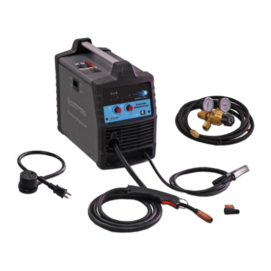
-Keep people with pacemakers away from your welding area when welding. -Do not wrap cable around your body while welding. -Wrap MIG gun and ground cable together whenever possible. -Keep MIG gun and ground cables on the same side of your body. Shielding Gas Cylinders Can Explode High pressure cylinders can explode if damaged, so treat them carefully. - Page 7 It features infinite wire feed speed control and voltage control, giving you total control to tune in the arc you want. The MMWM181DVI also features a cooling fan and thermal overload protection to help protect your investment. The Inverter Technology is evident from the moment you take this unit out of the box.
- Page 8 Power Indicator When the unit is plugged in and the power switch on the back panel is in the “On” position, the power indicator light will come on indicating power has been applied to the unit. Thermal Indicator If the duty cycle of the welder is exceeded the internal temperature will exceed safe temperatures and the machine will shut down.
-
Page 9: Installation
INSTALLATION Electrical Shock High voltage danger from power source! Consult a qualified electrician for proper installation of receptacle. This welder must be grounded while in use to protect the operator from electrical shock. Do not remove grounding prong or alter the plug in any way. Use only the supplied adapter between the plasma cutter's power cord and the power source receptacle. - Page 10 g. Reinstall the Drive Roller Cap and lock in place by turning it clockwise. h. Close the door to the welder drive compartment. 5. INSTALL THE WIRE a. Select welding wire - We recommend the usage of .030 Wire on this unit. However, .023 - .035 wire may be used.
- Page 11 wire secured on the edge of the spool. DO NOT UNHOOK IT AT THIS TIME. d. Place the spool on the spool hub so the wire will pull off the bottom of the spool. The welding wire should always come off the bottom of the spool into the drive mechanism.
- Page 12 j. Insert the wire into the inlet guide tube, feed it across the drive roller and into the torch assembly about six inches. -Make certain that the welding wire is actually going into the torch liner. If not, the wire will jam up in the mechanism. k.
-
Page 13: Gas Installation
8. GAS INSTALLATION Shielding gas cylinders and high pressure cylinders can explode if damaged, so treat them carefully. Never expose cylinders to high heat, sparks, open flames, mechanical shocks or arcs. Do not weld on the cylinder. Always secure cylinder upright to a cart or stationary object. - Page 14 g. Open the Gas Bottle Valve on the cylinder of gas. h. Turn the Gas Flow Adjuster on the regulator so that the gas flow rate is set at approximately 20 CFM. Make certain you are reading the correct scale on the gauge.
-
Page 15: Operation
OPERATION High voltage danger from power source! Consult a qualified electrician for proper installation of receptacle at the power source. This welder must be grounded while in use to protect the operator from electrical shock. If you are not sure if your outlet is properly grounded, have it checked by a qualified electrician. -
Page 16: Welding Techniques
6. DISTANCE FROM THE WORK PIECE - If the nozzle is held off the work piece, the distance between the nozzle and the work piece should be kept constant and should not exceed 1/4 inch or the arc may begin sputtering, signaling a loss in welding performance. 7. - Page 17 ELECTRIC SHOCK CAN KILL! To prevent ELECTRIC SHOCK, do not perform any welding while standing, kneeling, or lying directly on the grounded workpiece. 8.1 Moving the torch Torch travel refers to the movement of the torch along the weld joint and is broken into two elements: Direction and Speed.
- Page 18 8.3 Welding position FLAT POSITION is easiest of the welding positions and is most commonly used. It is best if you can weld in the flat position if at all possible as good results are easier to achieve. HORIZONTAL POSITION Is performed very much the same as the flat weld except that angle B (see HOLDING THE TORCH) is such that the wire, directed more toward the metal above the weld joint is to help prevent the weld puddle from running downward while still allowing slow enough travel speed.
- Page 19 falling into the nozzle. Angle B should be held at zero degrees so that the wire is aiming directly into the weld joint. If you experience excessive dripping of the weld puddle, select a lower heat setting. Also, the weave bead tends to work better than the stringer. 8.4 Multiple pass welding Butt Weld Joints When butt welding thicker materials, you will need to prepare the edges of the material to be joined by grinding a bevel on the edge of one or both pieces of the metal being joined.
- Page 20 8.5 Spot welding There are three methods of spot welding: Burn-Through, Punch and Fill, and Lap. Each has advantages and disadvantages depending on the specific application as well as personal preference. 1. The BURN-THROUGH METHOD welds two overlapped pieces of metal together by burning through the top piece and into the bottom piece.
-
Page 21: Maintenance
MAINTENANCE • Maintain your welder. It is recommended that the general condition of any welder be examined before it is used. Keep your welder in good repair by adopting a program of conscientious repair and maintenance. Have necessary repairs made by qualified service personnel. •... -
Page 22: Diagram & Parts List
DIAGRAM & PARTS LIST Page of 24... - Page 23 105200013 WIRE SPOOL HOLDER BOLT 27.5 105200014 WIRE SPOOL HOLDER END, FIXED 155200009 DOOR 155200013 WELD SET-UP CHART MMWM181DVI 105200080 DOOR LATCH 105200243 CENTER PANEL 155200014 OPERATOR'S MANUAL MMWM181DVI For replacement parts or technical questions, please contact our welder help line at 1-888-762-4045.
- Page 24 Distributed by CORNWELL QUALITY TOOLS 667 SEVILLE RD WADSWORTH OH 44281 www.conwelltools.com Made in China Page of 24...
Need help?
Do you have a question about the MMWM181DVI and is the answer not in the manual?
Questions and answers