Table of Contents

Related Manuals for Cornwell Tools MIG 250MGS


Summary of Contents for Cornwell Tools MIG 250MGS
- Page 1 MIG 250MGS OWNER’S MANUAL 2/2016 WARNING: Read carefully and understand all ASSEMBLY AND OPERATION INSTRUCTIONS before operating. Failure to follow the safety rules and other basic safety precautions may result in serious personal injury.
- Page 2 EFFECTIVE AUGUST 7, 2015 LIMITED WARRANTY This warranty applies to the original purchaser and is subject to the terms and conditions listed below. This Limited Warranty is for new equipment sold after the above date, providing coverage for defects in material and workmanship at the time it is shipped from the factory.
-
Page 3: General Safety Rules
GENERAL SAFETY RULES WARNING: Read and understand all instructions. Failure to follow all instructions listed below may result in serious injury. CAUTION: Do not allow persons to operate or assemble this MMWMGS250 until they have read this manual and have developed a thorough understanding of how the MIG/Stick 220Si works. - Page 4 -Connect ground lead as close to the area being welded as possible to ensure a good ground. -Do not allow any body part to come in contact with the welding wire if you are in contact with the material being welded, ground or electrode from another welder. -Do not weld if you are in an awkward position.
- Page 5 UV and IR Arc Rays The welding arc produces ultraviolet (UV) and infrared (IR) rays that can cause injury to your eyes and skin. Do not look at the welding arc without proper eye protection. -Always use a helmet that covers your full face from the neck to top of head and to the back of each ear.
-
Page 6: Technical Specifications
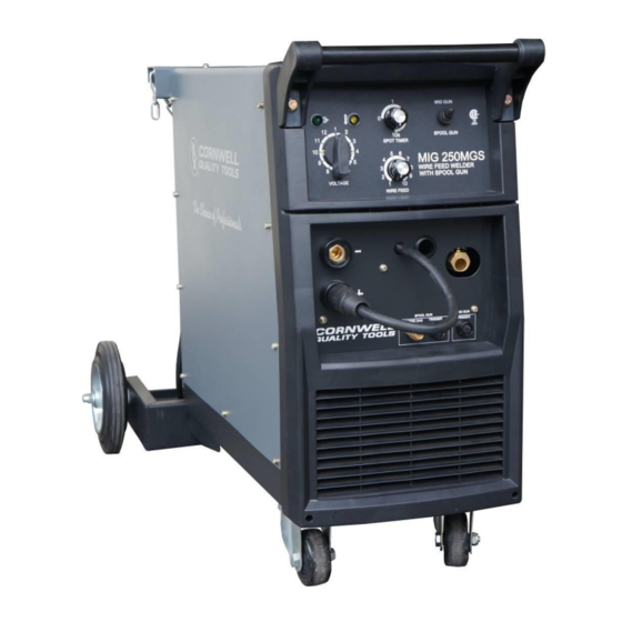
Electromagnetic Field -Electromagnetic fields can interfere with various electrical and electronic devices such as pacemakers. -Consult your doctor before using any electric arc welder or cutting device -Keep people with pacemakers away from your welding area when welding. -Do not wrap cable around your body while welding. -Wrap MIG gun and ground cable together whenever possible. - Page 7 DESCRIPTION The MMW250MGS is a light industrial DC MIG and FLUX CORE welder capable of welding up to 3/8" steel in a single pass. It requires 230 VAC (220-240), 60 Hz input power and a 50 Amp time delayed fuse or circuit breaker. This unit has built-in a dual bottle cylinder rack and built-in running gear for easy maneuvering.
- Page 8 POWER INDICATOR LIGHT In the “OFF” position no power is being supplied to the torch. In the “ON” position power is supplied to the main transformer and control circuit. PROTECTION INDICATOR LIGHT If the duty cycle of the welder is exceeded, the internal temperature will exceed safe temperatures and the machine will shut down.
- Page 9 ACCESSORY KIT This unit includes extra contact tips and extra drive rolls for different sizes of wire. DUAL CYLINDER RACK Holds two 7-1/2” diameter cylinders SPOOL GUN The spool gun holds 4 inch diameter spools of welding wire. Most commonly, the spool gun is used when welding aluminum.
- Page 10 Connect the ground cable to the Negative (-) weld output connection for MIG welding. If welding with self shielded flux core, connect the ground cable to the Positive (+) weld output connection and move the Weld Power Cable to the Negative (-) weld output connection. 1.6 Make certain the SPOOL GUN SELECTOR SWITCH on the front panel is switched into the MIG TORCH position.
-
Page 11: Installation
2.6 Connect the weld power connection to the bolt on the side of the MIG connector. 2.7 Connect the Spool Gun 5-Pin trigger connector to the Spool Gun 5-Pin receptacle on the front of the machine. 2.8 Connect the Spool Gun Quick Connect Gas Connector to the Spool Gun Gas Connection on the front of the machine. - Page 12 electrical codes for your specific area. Do not use an extension cord over 25 ft. in length. 3. INSTALL THE WIRE ROLLER - The wire roller has been factory installed. However, check to make certain the correct wire groove is in place to accommodate the size of wire you are using. Open the wire feed compartment.
- Page 13 Wire Diameter Roller Groove .023 .030 .035 .040 .045 3.7 Reinstall the Drive Roller knob and tighten clockwise. 3.8 Close the door to the welder drive compartment. 4. INSTALL THE WIRE - We recommend the usage of .023, .030, and .035 MIG wire, or .030, .035 and .040 flux core wire, on this unit.
- Page 14 4.2.5 The welder can use either 8 inch or 11 inch spools. The wire spool retainer secures the spool of wire onto the spool hub. The Wire Spool Tension Set Screw controls the tension on the spool. Wire Spool Tension Set Screw Wire Spool Retainer 4.2.6...
-
Page 15: Gas Installation
-The welding wire is electrically hot when the power is on and the torch trigger is activated. 4.2.16 Set the WIRE SPEED control to the middle of the wire speed range. 4.2.17 Straighten the MIG torch cable and pull the trigger in the gun handle to feed the wire through the torch assembly. - Page 16 connected to the negative (-) weld output connection. Refer to the polarity setting label inside the wire compartment. 6.1.2 Electrode Negative for Flux Core Welding - The Weld Power Cable should be connected to the negative (-) weld output connection on the front of the machine. The ground cable would then be connected to the positive (+) weld output connection.
-
Page 17: Operation
Mild steel: Use 75% Argon and 25% CO2 for reduced spatter and reduced penetration for thinner materials. Do NOT USE Argon gas concentrations higher than 75% on steel. The result will be extremely poor penetration, porosity, and brittleness of weld. Mild Steel: Use CO2 for deeper penetration but increased spatter. - Page 18 5.1. Angle a can be varied, but in most cases the optimum angle will be 60 degrees, the point at which the torch angle is parallel to the work piece. If angle A is increased, penetration will increase. If angle A is decreased, penetration will decrease also. 5.2.
-
Page 19: Welding Techniques
8. WELDING TECHNIQUES EXPOSURE TO A WELDING ARC IS EXTREMELY HARMFUL TO THE EYES AND SKIN! Prolonged exposure to the welding arc can cause blindness and burns. Never strike an arc or begin welding until you are adequately protected. Wear flame-proof welding gloves, a heavy long sleeved shirt, trousers with out cuffs, high topped shoes, and an ANSI approved welding helmet. - Page 20 The WEAVE BEAD Used when you want to deposit metal over a wider space than would be possible with a stringer bead. It is made by weaving from side to side while moving with the torch. It is best to hesitate momentarily at each side before weaving back the other way. 8.3 Welding position FLAT POSITION is easiest of the welding positions and is most commonly used.
- Page 21 VERTICAL POSITION It is easier for many people to Pull the torch from top to bottom. It can be difficult to prevent the puddle from running downward. Pushing the torch from bottom to top may provide better puddle control and allow slower rates of travel speed to achieve deeper penetration. When vertical welding, angle B (see HOLDING THE TORCH) is usually always kept at zero, but angle A will generally range from 45 to 60 degrees to provide better puddle control.
- Page 22 NOTE: WHEN USING SELF-SHIELDING FLUX-CORE WIRE it is very important to thoroughly chip and brush the slag off each completed weld bead before making another pass or the next pass will be of poor quality. Fillet Weld Joints. Most fillet weld joints, on metals of moderate to heavy thickness, will require multiple pass welds to produce strong joint.
-
Page 23: Spot Welding Instructions
1. The BURN-THROUGH METHOD welds two overlapped pieces of metal together by burning through the top piece and into the bottom piece. With the burn-through method, larger wire diameters tend to work better than smaller diameters. Wire diameters that tend to work best, with the burn-through method are 0.035 inch self-shielding flux-core wire. -
Page 24: Troubleshooting
TROUBLESHOOTING SYMPTOM POSSIBLE CAUSE CORRECTIVE ACTION Unit Does Not Power Up Unit Is Not Plugged In Plug In Unit Input Power Circuit Breaker Not On Reset Input Power Circuit Breaker The Main Power Switch Is Not Working Replace Main Power Switch Protection Indicator Is On The internal temperature is too high. -
Page 25: Diagram & Parts List
DIAGRAM & PARTS LIST Page of 28... - Page 26 REFERENCE # PART # DESCRIPTION 105200107 CENTER PANEL 105200108 ALUMINUM BUS BAR 105200109 CAPACITOR 105200110 WIRE SPOOL ASSEMBLY MOUNTING BRACKET 105200111 POWER SWITCH 105200112 STRAIN RELIEF 105200113 INERT GAS CONNECTOR 105200114 WIRE SPOOL ASSEMBLY 105200115 GAS VALVE 105100144 CYLINDER SUPPORT BRACKET 105100007 CYLINDER SECUREMENT CHAIN 4MM X .8M 105200116...
- Page 27 REFERENCE # PART # DESCRIPTION 105200146 RECTIFIER SUPPORT 105200147 THERMAL RELAY 105200148 MIG TORCH CONNECTOR 105200149 RESISTOR 105200150 WIRE DRIVE ASSEMBLY 105200162 DRIVE ROLL .023/.030 105200163 DRIVE ROLL .035/.045 155200004 ENCLOSURE 105200151 CONTROL TRANSFORMER 105200152 MAIN PC BOARD 105200153 AC CONTACTOR 105200154 MIG TORCH 105200155...
- Page 28 Distributed by CORNWELL QUALITY TOOLS 667 SEVILLE RD WADSWORTH OH 44281 www.conwelltools.com Made in China Page of 28...
Need help?
Do you have a question about the MIG 250MGS and is the answer not in the manual?
Questions and answers