Table of Contents
Advertisement
Quick Links
Advertisement
Table of Contents

Related Manuals for Cornwell Tools MMW180


Summary of Contents for Cornwell Tools MMW180
- Page 1 MMW180 OWNER’S MANUAL WARNING: Read carefully and understand all ASSEMBLY AND OPERATION INSTRUCTIONS before operating. Failure to follow the safety rules and other basic safety precautions may result in serious personal injury. WELDER WARRANTY...
-
Page 2: Limited Warranty
CORNWELL QUALITY TOOLS EFFECTIVE JANUARY 1, 2015 LIMITED WARRANTY This warranty applies to the original purchaser and is subject to the terms and conditions listed below. This Limited Warranty is for new equipment sold after the above date, providing coverage for defects in material and workmanship at the time it is shipped from the factory. -
Page 3: Important Safety Considerations
below may result in serious injury. CAUTION: Do not allow persons to operate or assemble this Flux Core 125 until they have read this manual and have developed a thorough understanding of how the Flux Core 125 works. WARNING: The warnings, cautions, and instructions discussed in this instruction manual cannot cover all possible conditions or situations that could occur. - Page 4 -Do not weld if you are in an awkward position. Always have a secure stance while welding to prevent accidents. Wear a safety harness if working above ground. -Do not drape cables over or around your body. -Wear a full coverage helmet with appropriate shade (see ANSI Z87.1 safety standard) and safety glasses while welding.
- Page 5 ear. -Use a lens that meets ANSI standards and safety glasses. For welders under 160 Amps output, use a shade 10 lens; for above 160 Amps, use a shade 12. Refer to the ANSI standard Z87.1 for more information. -Cover all bare skin areas exposed to the arc with protective clothing and shoes. Flame-retardant cloth or leather shirts, coats, pants or coveralls are available for protection.
-
Page 6: Technical Specifications
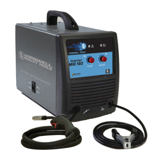
-Do not wrap cable around your body while welding. -Wrap MIG gun and ground cable together whenever possible. -Keep MIG gun and ground cables on the same side of your body. Shielding Gas Cylinders Can Explode High pressure cylinders can explode if damaged, so treat them carefully. -Never expose cylinders to high heat, sparks, open flames, mechanical shocks or arcs. - Page 7 DESCRIPTION The Cornwell MIG 180 is a portable DC wire feed welder capable of welding with solid wire (with shielding gas) or flux core wire. It uses leading edge Inverter Technology to provide high quality welds that are crisp, clean, and consistent with plenty of power and will impress the most experienced of welders.
-
Page 8: Installing The Handle
Welding Cable and Torch The welding wire is driven through the welding cable and torch to the work piece. It is attached to the drive system, the gun trigger activates the drive motor. Wire Speed Control Adjustment of the wire feed speed (amperage). ON/OFF Switch In the “OFF”... - Page 9 3. INSTALL THE WIRE ROLLER - The wire roller has been factory installed. However, check to make certain the correct wire groove is in place to accommodate the size of wire you are using. Open the wire feed compartment. Adjust the drive roller according to the following steps, see following picture about the wire feeder structure: 3.1 Open the door to the welder drive compartment 3.2 Remove the drive tension by loosening the drive tension adjusting knob (1) and lifting the Drive...
- Page 10 4.2 Installing the wire Electrical Shock Electric shock can kill! Always turn the POWER switch OFF and unplug the power cord • from the AC power source before installing wire. NOTE: - Before installing, make sure that you have removed any old wire from the torch assembly. This will help to prevent the possibility of the wire jamming inside the gun liner.
- Page 11 8 Inch 4 Inch 4.2.6 Setting the wire spool tension. a) Turn the spool of wire with one hand. b) Increase the spool tension by tightening (turn clockwise) the wing nut while turning the spool. Turn the spool while tightening the wing nut until the spool slows down and you feel a slight drag. Stop tightening the wing nut, you may need to repeat these steps until proper spool tension is achieved.
- Page 12 4.2.17 Straighten the MIG torch cable and pull the trigger in the gun handle to feed the wire through the torch assembly. When at least one inch of the wire sticks out past the end of the torch, release the trigger. 4.2.18 Turn the Power Switch to the OFF position.
- Page 13 6.2 Connect one end of the gas hose to the gas hose connection on the back of the welder. Connect the other end of the gas hose to the gas hose connection on the supplied regulator/flowgauge. 6.4 Before installing the regulator, it is good practice to make certain no debris is in the gas bottle connection.
-
Page 14: Operation
OPERATION High voltage danger from power source! Consult a qualified electrician for proper installation of receptacle at the power source. This welder must be grounded while in use to protect the operator from electrical shock. If you are not sure if your outlet is properly grounded, have it checked by a qualified electrician. -
Page 15: Welding Techniques
6. DISTANCE FROM THE WORK PIECE - If the nozzle is held off the work piece, the distance between the nozzle and the work piece should be kept constant and should not exceed 1/4 inch or the arc may begin sputtering, signaling a loss in welding performance. 7. - Page 16 ELECTRIC SHOCK CAN KILL! To prevent ELECTRIC SHOCK, do not perform any welding while standing, kneeling, or lying directly on the grounded workpiece. 8.1 Moving the torch Torch travel refers to the movement of the torch along the weld joint and is broken into two elements: Direction and Speed.
- Page 17 8.3 Welding position FLAT POSITION is easiest of the welding positions and is most commonly used. It is best if you can weld in the flat position if at all possible as good results are easier to achieve. HORIZONTAL POSITION Is performed very much the same as the flat weld except that angle B (see HOLDING THE TORCH) is such that the wire, directed more toward the metal above the weld joint is to help prevent the weld puddle from running downward while still allowing slow enough travel speed.
- Page 18 falling into the nozzle. Angle B should be held at zero degrees so that the wire is aiming directly into the weld joint. If you experience excessive dripping of the weld puddle, select a lower heat setting. Also, the weave bead tends to work better than the stringer. 8.4 Multiple pass welding Butt Weld Joints When butt welding thicker materials, you will need to prepare the edges of the material to be joined by grinding a bevel on the edge of one or both pieces of the metal being joined.
- Page 19 8.5 Spot welding There are three methods of spot welding: Burn-Through, Punch and Fill, and Lap. Each has advantages and disadvantages depending on the specific application as well as personal preference. 1. The BURN-THROUGH METHOD welds two overlapped pieces of metal together by burning through the top piece and into the bottom piece.
-
Page 20: Maintenance
MAINTENANCE • Maintain your MIG 180. It is recommended that the general condition of any welder be examined before it is used. Keep your welder in good repair by adopting a program of conscientious repair and maintenance. Have necessary repairs made by qualified service personnel. - Page 21 MAIN CIRCUIT CHART Page of 24...
-
Page 22: Diagram & Parts List
DIAGRAM & PARTS LIST Page of 24... - Page 23 Reference # Description Part Number Qty. Handle 2.05.05.970 Case cover, enclosure 1.1.01.02.0338-C Gas Valve connector 1.1.01.05.3023 Electric Cable Clamp 2.05.05.200 Power Cord 1.2.07.01.2885 Main Switch 2.07.80.001 1.2.07.02.3854 Back Panel 1.1.01.03.1651 Wire feeder wiring 2.03.30.723 Main PC Board 1.1.05.02.0196-1 Control Board 1.1.05.02.0177 Sheet metal case base 1.1.01.04.1326...
- Page 24 Distributed by CORNWELL QUALITY TOOLS 667 SEVILLE RD WADSWORTH OH 44281 www.conwelltools.com Made in China Page of 24...
Need help?
Do you have a question about the MMW180 and is the answer not in the manual?
Questions and answers