Table of Contents
Advertisement
Advertisement
Table of Contents

Related Manuals for Wickes BMS2102


Summary of Contents for Wickes BMS2102
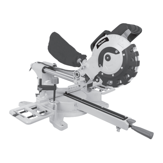
- Page 1 SLIDING MITRE SAW 210MM BMS2102 223747...
-
Page 2: Table Of Contents
CONTENTS GENERAL POWER TOOL SAFETY WARNINGS COMPONENT LIST ACCESSORIES TECHNICAL DATA SYMBOLS NOISE INFORMATION OPERATING INSTRUCTIONS MAINTENANCE ENVIRONMENTAL PROTECTION PLUG REPLACEMENT (ONLY FOR REWIRABLE PLUG OF UK & IRELAND) DECLARATION OF CONFORMITY... -
Page 3: General Power Tool Safety Warnings
ORIGINAL INSTRUCTION GENERAL POWER TOOL SAFETY WARNINGS WARNING: Read all safety warnings, 3) Personal safety instructions, illustrations and specifications a) Stay alert, watch what you are doing and use provided with this power tool. Failure to follow all common sense when operating a power tool. instructions listed below may result in electric shock, fire Do not use a power tool while you are tired or under and/or serious injury. - Page 4 and/or remove the battery pack, if detachable, from the power tool before making any adjustments, changing accessories, or storing power tools. Such preventive safety measures reduce the risk of starting the power tool accidentally. d) Store idle power tools out of the reach of children and do not allow persons unfamiliar with the power tool or these instructions to operate the power tool.
- Page 5 j) Ensure the mitre saw is mounted or placed on a level, firm work surface before use. A level and firm work surface reduces the risk of the mitre saw becoming unstable. k) Plan your work. Every time you change the bevel or mitre angle setting, make sure the adjustable fence is set correctly to support the workpiece and will not interfere with the blade or the guarding system.
-
Page 6: Component List
COMPONENT LIST... -
Page 7: Accessories
Operating handle Bevel lock lever Lower blade lock lever Slide rod Upper fixed guard Dust extraction port Lower rotating guard Dust bag Blade bolt cover Carry handle Fence Release knob Base plate Slide rod lock knob Rotating mitre table Spindle lock button Mitre table lock latch On/off switch Mitre table lock handle... -
Page 8: Technical Data
TECHNICAL DATA Rated voltage 230-240V~50Hz Rated Input power S1:1450W, S6:1800W No load speed 5000/min Bevel capacity 0-45º Blade size 210mm Protection class Machine weight 11kg Cutting capacity Max cutting capacity mitre/bevel: 0º/90º 62*310mm Max cutting capacity mitre/bevel: 0º/45º 34*310mm Max cutting capacity mitre/bevel: 45º/45º 34*215mm Max cutting capacity mitre/bevel: 45º/90º... -
Page 9: Noise Information
NOISE INFORMATION A weighted sound pressure : 97 dB(A) A weighted sound power : 110 dB(A) & K 3.0 dB(A) Wear ear protection. The declared noise emission value has been measured in accordance with a standard test method and may be used for comparing one tool with another. -
Page 10: Operating Instructions
OPERATING INSTRUCTIONS NOTE: Before using the tool, read the instruction book carefully. Intended Use The machine is intended as a stationary machine for making straight lengthways and crossways cuts in wood. Horizontal mitre angles of -45° to +45° as well as vertical bevel angles of 0° to +45° are possible. ASSEMBLY WARNING: To prevent the accidental starting that could cause possible serious personal injury, ALWAYS assemble all parts to your saw BEFORE connecting it to the power supply. - Page 11 Fig. B2 Fig. B1 Fig. B3 Fig. B4 3. WORK CLAMP (SEE FIG. C) Fig. C When cutting workpieces, they should always be clamped with a work clamp. The work clamp can be fitted on either side of the saw and is fully adjustable to suit the size of the workpiece.
- Page 12 4. MOUNTING BOLT (SEE FIG. D) Before use, the mitre saw can be fixed to a firm, level and stable supporting surface, such as a workbench. Four mounting holes have been provided in the saw base for this purpose. Each of these four mounting holes should be securely bolted using appropriate machine bolt with suitable lock washer and hex nut (not supplied).
- Page 13 2. MITRE TABLE LOCK (SEE FIG. F1, F2) The mitre table lock latch is used to lock the table at the desired mitre angle. NOTE: Assemble the mitre table lock handle before adjusting mitre angle. Insert the handle into the lock arm and tighten it.
- Page 14 Fig. G3 Fig. G4-1 Fig. G4-2 4. SPINDLE LOCK BUTTON (SEE FIG. H) The spindle lock button prevents the blade in the saw from rotating. Depress and hold the spindle lock button while installing, changing, or removing the blade. Fig. H 5.
- Page 15 7. LASER GUIDE(SEE FIG. K1, K2) Fig. K1 Press the laser on/off switch to turn the laser on. The laser device can provide a beam in the same plane as the blade, which projects onto the workpiece to generate a line. The saw blade can be directed to follow the line in order to align the cut.
- Page 16 Fig. E2 2. CHOP CUT (SEE FIG. M1, M2) Chop cut is used mainly for narrow pieces, i.e. the slide rod lock knob is tightened and the saw head is lowered to cut through the workpiece. 1) Connect the machine to power outlet ensure that the mains cable is clear of the blade and base plate.
- Page 17 3. CROSS PULL CUT (SEE FIG. N1, N2) Cross pull cut is used mainly for wide pieces, allowing you to cut wider pieces of wood, i.e. the slide rod lock knob is loose, the saw head is pulled towards the operator, the saw head is lowered to the workpiece and then pushed to the rear of saw to make a cut to do this, follow the procedures below:...
- Page 18 Fig. P 5. BEVEL CUT (SEE FIG. P) A bevel cut can be made at any angle in the range of 0° to 45° left. It can be made as either a chop cut or a cross pull cut depending on the width of the workpiece. The saw can be moved from the normal 0°...
-
Page 19: Maintenance
MAINTENANCE Remove the plug from the socket before carrying out any adjustment, servicing or maintenance. There are no user serviceable parts in your power tool. Never use water or chemical cleaners to clean your power tool. Wipe clean with a dry cloth. Always store your power tool in a dry place. Keep the motor ventilation slots clean. Keep all working controls free of dust. - Page 20 2. CHANGING THE SAW BLADE (SEE FIG. T1-T4) Fig.T1 WARNING: To prevent personal injury, always disconnect the plug from power source before assembling parts, making adjustments or changing blades. 1) Unplug the saw from the power supply. 2) Release and raise the saw head to its fully raised position.
-
Page 21: Environmental Protection
ENVIRONMENTAL PROTECTION Waste electrical products should not be disposed of with household waste. Please recycle where facilities exist. Check with your Local Authority or retailer for recycling advice. PLUG REPLACEMENT (ONLY FOR REWIRABLE PLUG OF UK & IRELAND) If you need to replace the fitted plug then follow the instructions below. IMPORTANT The wires in the mains lead are colored in accordance with the following code: Blue = Neutral... -
Page 22: Declaration Of Conformity
DECLARATION OF CONFORMITY Wickes Building Supplies Limited Declare that this product: SLIDING MITRE SAW Description and SKU code: 223747 Complies with the following Directives and Regulations: 2006/42/EC, Machinery Directive 2014/30/EU, Electromagnetic Compatibility Directive 2011/65/EU & (EU)2015/863 (RoHS), Restriction of Hazardous Substances Directive... - Page 24 Customer Helpline 0345 2005409...
Need help?
Do you have a question about the BMS2102 and is the answer not in the manual?
Questions and answers