Advertisement
Quick Links
MAXIMUM PRODUCT LOAD RATING: 100 kg
IMPORTANT:
•
LOAD = WEIGHT OF PLATFORM or BARS + MOUNTING SYSTEM + ACCESSORIES + CARGO
•
PLEASE REFER TO VEHICLE MANUFACTURER SPECIFICATIONS FOR MAX ROOF
LOAD CAPACITY OF VEHICLE. THE LOWEST LOAD RATING APPLIES.
•
OFFROAD RATING: SCAN QR CODE FOR LOCKNLOAD LOAD RATING GUIDE.
REDUCTIONS MAY APPLY.
IF NO TRACK PROVIDED THIS MOUNTING KIT REQUIRES AN 800 MM OR 1000 MM LONG UNIVERSAL TRACK TO BE
INSTALLED FIRST. NOTE: THE UPPER SURFACE OF THE TRACK NEEDS TO BE WITHIN +/- 2 DEGREES OF FLAT, LEFT TO RIGHT.
•
Please read instructions carefully before installation.
•
Check the contents of kit. Each spine has the last four digits of the kit's part number lasered in.
Contact your YAKIMA dealer if any parts appear missing, incorrect or damaged.
•
Clean your roof thoroughly prior to fitting the LockNLoad RuggedLine.
•
Place these instructions in the vehicle's glove box after installation is complete.
TOOLS REQUIRED:
• 13 mm Spanner
ITEM COMPONENT
1.
Track 1200 mm Spine LH 2172
2.
Track 1200 mm Spine RH 2172
3.
Pivot Bracket Assembly
4.
M8 Socket Head Capscrew
5.
M8 Washer
6.
M8 Nyloc Nut
7.
M6 Self Aligning T-Bolt
2
13
12
NOTE: ITEMS 3, 4, 5 & 6 ARE FOR USE ON A PLATFORM INSTALLATION.
ITEMS 10 & 11 ARE FOR AN LNL BAR INSTALLATION.
6100014323_9812172_Rev2
®
FIRST TIME INSTALLATION
KIT CONTENTS
QTY ITEM COMPONENT
x1
8.
x1
9.
x4
10.
x4
11.
x8
12.
x4
13.
x8
3
1
6
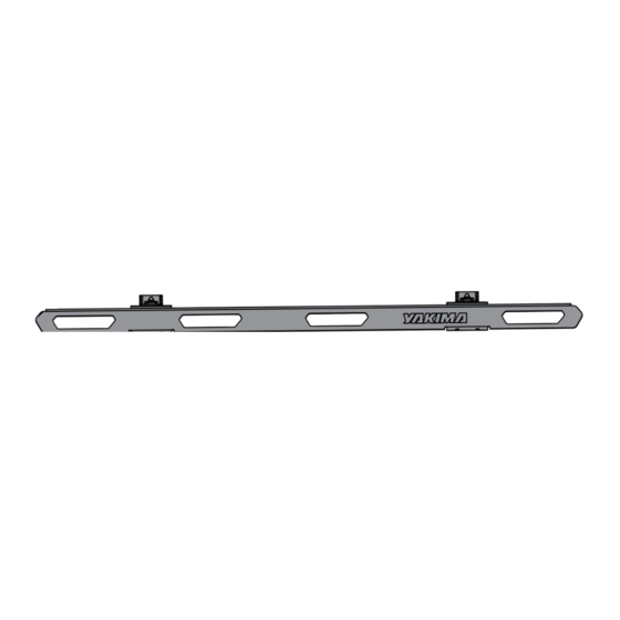
LockNLoad™ RuggedLine®
RuggedLine Flat 1200mm
M6 Nyloc Nut
M6 Flat Wash
LNL Flush Rail Bar Slot Bolt
LNL Flush Rail Bar Slot Plate
Hex Key Ball End Allen Key 4 mm
Hex Key Ball End Allen Key 6 mm
4
5
10
11
8
9
7
CARGO
QTY
x8
x8
x4
x4
x1
x1
1/9
Advertisement

Related Manuals for Yakima LockNLoad RuggedLine Flat 1200mm


Summary of Contents for Yakima LockNLoad RuggedLine Flat 1200mm
- Page 1 • Check the contents of kit. Each spine has the last four digits of the kit’s part number lasered in. Contact your YAKIMA dealer if any parts appear missing, incorrect or damaged. • Clean your roof thoroughly prior to fitting the LockNLoad RuggedLine.
- Page 2 RUGGEDLINE SPINE INSTALLATION INSERT SELF ALIGNING T BOLT REMOVE STOPPER Inset M6 Self Sligning T Bolt into Remove track stopper if applicable the end of the track and slide into position along the track.. POSITION RUGGEDLINE SPINE ON VEHICLE TRAY Referring to the left-right orientation on top of each blade, carefully place one side RuggedLine Spine onto vehicle tray sides (or canopy) as shown.
- Page 3 TIGHTEN RUGGEDLINE SPINE HARDWARE Using the 10 mm Spanner, and avoiding damage to the powder coat, start to carefully secure the RuggedLine Spine by tightening the M6 Nylock nut to 7 Nm into the mounting holes in tray. Turn Spanner carefully and be sure not to damage the Nut.
- Page 4 PLATFORM INSTALLATION ASSEMBLE PIVOT BRACKET SECURE PIVOT BRACKET TO RUGGEDLINE ASSEMBLIES Assemble Pivot Bracket and M8 Tighten all Capscrews hardware as pictured. Complete with the provided 6 mm this for both M8 mounting holes T Handle Ball End Allen on top of the RuggedLine Spine. Key, and all Nuts with a 13 mm Spanner or a suitable Torque...
- Page 5 SECURE PLATFORM PIVOT MOUNTS Secure all Platform Pivot Mounts with 2x 16 mm M6 Capscrews with Washer from LockNLoad Platform kit as shown. Tighten all Capscrews to 4 Nm with the provided 4 mm Ball End Allen Key or a suitable Torque Wrench. NOTE - The Pivot Mount assembly will still have movement after securing...
- Page 6 LOCKNLOAD BAR INSTALLATION REMOVE END CAPS FROM BARS From the LockNLoad TrimHD kit (sold separately), remove Plastite Screw from each bar end using a #2 Phillips Head Screwdriver and pull out End Caps from bars. Keep all parts aside for later installation. REMOVE INFILL Remove infill from underside of the TrimHD bar.
- Page 7 BAR FITMENT Bar placement should be a minimum of 700 mm apart from one another. INSERT INFILL Cut infill into four pieces according to the measurement taken in Step 3. Insert into underside channel of front and rear bar ends as shown. NOTE - Bar Slot Covers to be inserted with flat side visible INSERT SLOT BOLT AND SLOT PALTE...
- Page 8 INSERT LEGS Insert the T-Bolt into the Atlas Slide-Away blade. SECURE SLOT BOLT AND SLOT PLATE Using the 10 mm Spanner, secure the plate and bolt to the RuggedLine Spine. CHECK BAR LEGS ARE SECURE Check all Bar Legs are secure. 6100014323_9812172_Rev2...
- Page 9 YAKIMA AUSTRALIA PTY LTD 17 Hinkler Court Brendale, QLD 4500 Australia 1800 143 548 yakimaglobal.com YAKIMA PRODUCTS, INC. 4101 Kruse Way Lake Oswego, OR 97035-2541 888 925 4621 yakima.com/support ALL CONTENT SUBJECT TO YAKIMA AUSTRALIA PTY LTD COPYRIGHT © 2023 6100014323_9812172_Rev2...
Need help?
Do you have a question about the LockNLoad RuggedLine Flat 1200mm and is the answer not in the manual?
Questions and answers