Advertisement
Quick Links
Advertisement

Related Manuals for Pentair AURORA Edwards 20


Summary of Contents for Pentair AURORA Edwards 20
- Page 1 Edwards Model 20 / Model 80 Pump Maintenance Manual...
- Page 3 Contents Installation Safety Inspection ..... . 3-1 General Precautions ....iii Unpacking .
- Page 5 Safety General Precautions The following are general safety precautions not related to any specific procedure. Per- sonnel must understand and apply these precautions during both operation and main- tenance of the pump. Do Not Operate Pump Without Ear Protection. The pump has heat-treated steel timing gears, which can be very noisy when operated above 900 rpm.
- Page 6 Model 20 / Model 80 Pumps Do not order parts using this manual if the model number on the pump is not 20-420 or the serial number is not ________________. Using parts ordered from the wrong manual could result in pump failure or personal injury. Cautions Do not hammer on pump endcase.
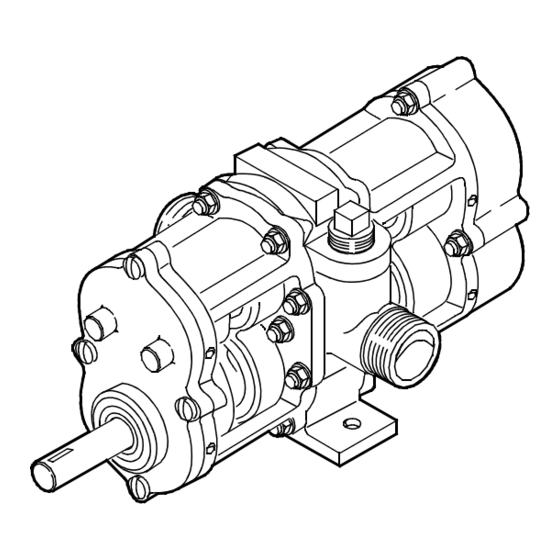
- Page 7 General Introduction The Edwards Model 20 and Model 80 pumps (Figure 1-1) are standard-duty high-speed gear-driven positive-displacement rotary pumps with gear-type rotors. The pumps are self-priming. Edwards rotary pumps are available in many configurations. While they may look alike, there may be significant differences from one pump to another. Differences include construction material, sealing method, rotor type, etc.
- Page 8 20-420 and the serial number is ________________. If the numbers do not match, contact Edwards - Pentair Water. Most pump repairs can be performed by maintenance personnel using normally avail- able tools.
- Page 9 Table 2-2. If the pump is operating at over 180°F, contact over-greased. Edwards - Pentair Water for recommended lubrication interval for your application. Excess grease will run out of the fit- Table 2-2. Lubrication Schedule ting when pump is in operation.
- Page 10 Maintenance Table 2-3. Troubleshooting (Continued) Trouble Probable Cause Remedial Action 2c. Worn or damaged 2c. Repair or replace pump. bearing(s). Excessive 3a. Loose or misaligned 3a. Tighten, align, or replace vibration coupling. coupling. 3b. Cavitation. 3b. Check suction piping with a vacuum gauge.
- Page 11 Model 20 / Model 80 Pumps Disassembly General Practice 1. Keep work area as clean as possible to avoid contamination of internal parts. 2. Replace gaskets, packings, and seals removed during repair. Replace all keys, spring washers, and like items during assembly. 3.
- Page 12 Maintenance UPPER DRIVE SUCTION DISCHARGE DISCHARGE PORT PORT PORT LEFT HAND RIGHT HAND ROTATION ROTATION LOWER DRIVE SUCTION DISCHARGE SUCTION PORT PORT PORT LEFT HAND RIGHT HAND ROTATION ROTATION 1070_0002a.cdr NOTE: ALL ROTATIONS ARE VIEWED FROM PUMP SHAFT END. Edwards USES THE FOLLOWING NOTATION FOR PUMP IDENTIFICATION: UR = UPPER SHAFT –...
- Page 13 Model 20 / Model 80 Pumps 1’’ THRU 3/8’’ HOLES 5/16’’ x 1-3/4’’ NC GRADE 8 (2 PLACES) CAP SCREWS (2 PLACES) 1-5/8’’ 3/4’’ 4’’ 1-1/2’’ 1070_0003b.cdr Figure 2-2. Timing-Gear Puller Plate Fabrication Diagram 12. Remove cap screws (18), nuts (3), and washers (19) from timing gear endcase (17). 13.
- Page 14 Maintenance 2. After soaking parts in “dry” cleaning solvent, deposits may be washed away by flushing or spraying. Where necessary, use soft-bristled, non-metallic brush moist- ened in solvent. 3. Except for bearings, dry parts using filtered, compressed air after cleaning. 4.
- Page 15 Model 20 / Model 80 Pumps Assembly General Practice 1. Remove any protective coatings from new parts. 2. Lubricate bearings with same type of lubricant normally used in pump or as directed in specific repair procedure. 3. Lubricate lip of oil seals with lubricant specified in specific procedure. Install oil seals, with lip facing out, by applying an even force to outer edge of seal.
- Page 16 Figure 2-4. We recommend using an arbor press to seat the seals. Installation tools are available from Edwards-Pentair Water. face toward pump body as shown in 3.
- Page 17 Model 20 / Model 80 Pumps Install Endcases 1. Install new pump body gasket (21) to each side of the body (27). 2. Install large flat washer and nut (3) on one of the studs (26) on timing-gear end of pump body (27).
- Page 18 Maintenance 5. Slowly tighten adjusting nut opposing adjusting nut tightened during step 4 until slight opposite dial indicator needle movement is observed. Do not overtighten. Do not overtighten bearing adjusting nut setscrews. Excessive bearing preload may result, causing bearing damage. 6.
- Page 19 Model 20 / Model 80 Pumps 6. After all lash has been removed, hold idler timing gear (11) in place while seating gear by lightly tapping it with a bearing seating sleeve. 7. Apply anti-seize compound (4, Table 2-10) to timing gear locknut (9, Figure 4-1) threads and install locknut on idler shaft.
- Page 20 2. Check for shipment shortages against the bill of lading. 3. Report shortages to the carrier and note them on the bill of lading. 4. Notify Edwards - Pentair Water of damage to contents not a fault of the carrier, or in the event of short- ages.
- Page 21 Model 20 / Model 80 Pumps 3. Leave plastic or gasket-type port covers in place. 4. If pump comes wrapped with protective material, rewrap pump. 5. Store in clean, dry location. Installation The pump can be installed wherever adequate space exists to connect piping and per- form maintenance.
- Page 22 Installation 13.75’’ 8.625’’ 7.25’’ 5.0’’ 3.75’’ 2.5’’ 1.75’’ 0.625’’ 4.5’’ 5.625’’ 1070_0006b.cdr Figure 3-2. Edwards Model 20 Dimensions 5.63’’ 2.81’’ 2.25’’ 2.25’’ C L PUMP C L PUMP 1.75’’ 0.87’’ 0.38’’ HOLES 1070_0007b.cdr Figure 3-3. Edwards Model 20 Mounting Bolt Locations...
- Page 23 Model 20 / Model 80 Pumps Prepare Foundation The foundation absorbs any vibration, strains, or shock, while providing a permanent, rigid support for the pump skid. 1. Construct a foundation form that is 4 to 6 inches longer and wider than the skid base.
- Page 24 Installation PUT WASTE 1/2’’ AROUND BOLT TEMPLATE BEFORE POURING CONCRETE LEAVE SURFACE ROUGH TO ANCHOR GROUT SLEEVE 5’’ 1.5’’ WASHER 1/4’’ 2’’ 3’’ 1070_0011a.cdr Figure 3-5. Typical Foundation Bolt Configuration Level Pump Skid 1. Before pump skid is set on foundation, clean underside of skid base and top of foun- dation.
- Page 25 Model 20 / Model 80 Pumps 3. Wet top of foundation prior to grouting. 4. Pour grout between frame and skid base. 5. Puddle grout as poured, working as much as possible under skid base and into sleeves around foundation bolts. Ideally, complete space under skid base should be filled to height of grout around skid base.
- Page 26 Installation 4. Start and stop the driver while observing driver shaft rotation. Driver rotation must be same as pump rotation. For applications Align Couplings where pumps are operated at elevated The alignment of the pump and motor or engine driver must be checked before startup. temperatures, final Maximum angular offset in the two coupling halves is 1 degree;...
- Page 27 Model 20 / Model 80 Pumps FEELER GAUGE 1070_0014a.cdr Figure 3-8. Checking for Angular Coupling Misalignment Checking for Parallel Misalignment. To check parallel misalignment: 1. Attach dial indicator as shown in Figure 3-9. 2. With dial indicator secured to pump or driver shaft, rotate both shafts together, noting dial indicator readings through one complete revolution.
- Page 28 Installation USE DIAL SECURE BRACKET INDICATOR TO COUPLING HALF FOR PARALLEL ALIGNMENT USE INSIDE MICROMETER FOR ANGULAR ALIGNMENT 1070_0016a.cdr Figure 3-10. Checking for Spacer Coupling Misalignment Piping Rotary pumps have close running clearances. Thus, clean piping is a must. Dirt, grit, weld bead or scale, flushed from an unclean piping system, will damage and may stall the pump.
- Page 29 Model 20 / Model 80 Pumps tem including valves, strainers, and other restrictions, and the elevation of the pump with reference to supply and discharge points. Friction or line losses may be calculated by referring to the manufacturer’s Engineering Manual or the Hydraulic Institute’s Engineering Data Book.
- Page 30 Installation RECOMMENDED BYPASS FLOW SUPPLY TANK PRESSURE RELIEF VALVE NOT RECOMMENDED BUSHING PIPE TEE TO SYSTEM SUCTION PORT DISCHARGE PORT ROTARY GEAR PUMP 1070_0005a.cdr Figure 3-11. Pump By-pass Piping Pre-Startup Checks Inspection checks are essential to avoid operational difficulties and ensure trouble-free startup.
- Page 32 Check the name plate on the pump to make certain the model number is 20-420 and the serial number is ________________. If the numbers do not match, contact Edwards - Pentair Water. When ordering parts, please provide: 1.
- Page 33 SECTION EDWARDS PAGE 4 DATED JANUARY 2008 Figure 4-1. Edwards Model 20 Pump Exploded View 1070_0008a.cdr Pentair Water...
- Page 34 20-418 700-0856 644 ** 20-420 700-0858 644 ** Rotor Assembly - Idler 20-412 700-0851 644 ** 20-414 700-0853 644 ** 20-416 700-0855 644 ** 20-418 700-0857 644 ** 20-420 700-0859 644 ** BOLD numbers are recommended spare parts. Pentair Water...
- Page 35 SECTION EDWARDS PAGE 6 DATED JANUARY 2008 Figure 4-2. Edwards Model 80 Pump Exploded View 1070_0008e.cdr Pentair Water...
- Page 36 80-440 700-0866 644 ** Rotor Assembly - Idler 80-424 700-0861 644 ** 80-428 700-0863 644 ** 80-432 700-0865 644 ** 80-440 700-0867 644 ** 25 Pipe Plug (part of No. 27) 600-0006 BOLD numbers are recommended spare parts. Pentair Water...
- Page 38 WARRANTY: Seller warrants equipment (and its component parts) of its own manufacture against defects in materials and workmanship under normal use and service for one (1) year from the date of installation or start-up, or for eighteen (18) months after the date of shipment, whichever occurs first.
- Page 39 800 Airport Road, North Aurora, IL 60542 phone: 630-859-7000 fax: 630-859-1226 website: www.AuroraPump.com ED11005 (07/08/13)
Need help?
Do you have a question about the AURORA Edwards 20 and is the answer not in the manual?
Questions and answers