Table of Contents
Advertisement
Quick Links
Advertisement
Table of Contents

Related Manuals for Multitech RBS3010NA01BN00


Summary of Contents for Multitech RBS3010NA01BN00
- Page 1 Radio Bridge ® LoRaWAN Wireless Sensor Door Window Sensor User Guide...
- Page 2 Multi-Tech Systems, Inc. All rights reserved. Copyright © 2023 by Multi-Tech Systems, Inc. Trademarks and Registered Trademarks MultiTech, the MultiTech logo, DeviceHQ, and Conduit are registered trademarks of Multi-Tech Systems, Inc. All other products and technologies are the trademarks or registered trademarks of their respective holders.
-
Page 3: Table Of Contents
CONTENTS Contents Chapter 1 – Overview .............................. 5 Sensor Overview ................................5 Documentation ................................5 Part Numbers ................................5 Chapter 2 – Quick Start............................6 Preparing an RBS301 Sensor............................6 Quick Start..................................6 Mounting the Sensor ..............................7 Chapter 3 – Hardware Specifications and Information ..................... 8 Absolute Maximum Ratings ............................ - Page 4 CONTENTS Chapter 7 – Regulatory Information........................22 47 CFR Part 15 Regulation Class B Devices ......................... 22 Federal Communications Commission (FCC) ......................22 Industry Canada Class B Notice........................... 23 EMC, Safety, and R&TTE Directive (RED) Compliance ....................23 Standards .................................. 23 Harmonized Commodity Description (HS Code)......................
-
Page 5: Chapter 1 - Overview
The LoRaWAN Wireless Door/Window Sensor uses a magnetic Hall effect sensor to detect open/close events for doors and windows. When an open or close event is detected, an alert is sent over the wireless network. Documentation The following documentation is available at https://www.multitech.com/products/sensors. Document Description... -
Page 6: Chapter 2 - Quick Start
Use your sensor through either the console or a third-party network. To use the console, use the following steps. To use a third-party network, refer to the Connecting LoRaWAN Sensors on Gateways and Networks (RB00001) , which is available through the sensor page at https://www.multitech.com/products/sensors Create a console account at: https://console.radiobridge.com/ Click on Devices on the left. -
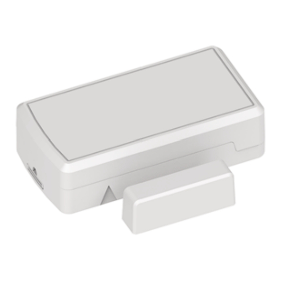
Page 7: Mounting The Sensor
QUICK START Mounting the Sensor The window/door sensor includes a sensor and a magnet that need line up. Use the included large adhesive pad to secure the sensor case on the door or window frame with the notch facing the door or window as shown. For increased security using the included tamper screw: Open the case. -
Page 8: Chapter 3 - Hardware Specifications And Information
HARDWARE SPECIFICATIONS AND INFORMATION Chapter 3 – Hardware Specifications and Information Absolute Maximum Ratings Parameter Rating Operating ambient temperature (indoor version) -30°C to +70°C Operating ambient temperature (outdoor version) -40°C to +70°C Storage ambient temperature -40°C to +90°C Battery Life The sensor uses a lithium non-rechargeable battery, capable of an estimated 200,000+ messages. -
Page 9: Replacing The Battery
HARDWARE SPECIFICATIONS AND INFORMATION Replacing the Battery Replacement battery type is listed in the Battery Life topic. To replace the battery: Use a pen or similar object to press the button on the opposite side of the case. Remove the battery. Insert the new battery as shown. -
Page 10: Mechanical Drawings
HARDWARE SPECIFICATIONS AND INFORMATION Mechanical Drawings The mechanical drawings provided in this section are for the main body of the sensor. All dimensions use inches unless specified. Indoor RBSx01 Sensors ® Radio Bridge LoRaWAN Wireless Sensor Door Window Sensor User Guide... -
Page 11: Chapter 4 - Safety
Lithium cells and batteries are subject to the Provisions for International Transportation. Multi-Tech Systems, Inc. confirms that the Lithium batteries used in the MultiTech product(s) referenced in this manual comply with Special Provision 188 of the UN Model Regulations, Special Provision A45 of the ICAO-TI/IATA[1]DGR (Air), Special Provision 310 of the IMDG Code, and Special Provision 188 of the ADR and RID (Road and Rail Europe). -
Page 12: Chapter 5 - Common Messages
Chapter 5 – Common Messages Common Messages This chapter defines the protocol and message definitions common to all MultiTech wireless sensors. Common messages include basic error messages, tamper, supervisory, link quality, and downlink acknowledgments. Sensor specific messages are in the Sensor Specific Messages chapter. -
Page 13: Reset Message (0X00)
COMMON MESSAGES Message Type Payload Description 0xfb Link quality Sent after each downlink configuration (refer to Link Quality Message) or to periodically ping the network server (refer to Link Quality Check Period). 0xfe Reserved. 0xff 1-byte status Downlink message ACK. Refer to Downlink ACK for more detail. -
Page 14: Supervisory Message (0X01)
COMMON MESSAGES Supervisory Message (0x01) Wireless sensors periodically (19 hours by default) send a supervisory message so the backend system can verify the device is still alive and report error conditions. The supervisory message payload include current sensor status. You can also trigger a supervisory message. To do this: Place a magnet near the triangular notch on the side of the sensor. -
Page 15: Downlink Ack (0Xff)
COMMON MESSAGES Downlink ACK (0xFF) The cloud app uses this downlink ACK message to verify the that sensor received the downlink message received and it was considered valid. The sensor replies to the downlink data with a 0xFF message (downlink ACK) with the payload shown in the following table. -
Page 16: General Configuration
COMMON MESSAGES General Configuration Use the general configuration command to configure parameters that apply to all sensor types. Byte Description 0x00 Disable sensor events 0x01 Radio config 0x02 Supervisory period. Default 19 hours. 0x03 Sampling rate ® Radio Bridge LoRaWAN Wireless Sensor Door Window Sensor User Guide... - Page 17 COMMON MESSAGES Disable Sensor Events The following table shows the disable sensor event bit definitions. Description Not used Disable all sensor events Radio Config The following table shows the radio config byte definition. Note: Available in firmware version 1.4 or newer. Bits Description Not used (reserved)
- Page 18 COMMON MESSAGES Refer to the Battery Estimator for battery life estimates relative to sampling rate: https://radiobridge.com/documents/Sensor%20Battery%20Estimator.xlsx A value of 0 in this field leaves the sampling rate at the current value. Use the following table to determine the sampling rate if the value is not zero. Note: Sampling period only applies to sensors that take measurements like temperature and tilt, it does not apply to sensors with binary inputs such as door/window sensors or push buttons.
-
Page 19: Device Info Request
COMMON MESSAGES Device Info Request The Device Info Request command is a downlink to inform the gateway to report its downlink configuration information. Description 0x00 Downlink configuration type to request. 0-254: Request device info for specific downlink type to report. 255: Request device info for all downlink configurations. -
Page 20: Adr Advanced Configuration
COMMON MESSAGES ADR Advanced Configuration The ADR configuration message overrides the LoRaWAN ADR_ACK_LIMIT and ADR_ACK_DELAY parameters. Byte Description 0x00 ADR_ACK_LIMIT value when running in Unconfirmed Mode. The default value is 64. 0x01 ADR_ACK_DELAY value when running in Unconfirmed Mode. The default value is 32. 0x02 ADR_ACK_LIMIT value when running in Confirmed Mode. -
Page 21: Chapter 6 - Sensor-Specific Messages
SENSOR-SPECIFIC MESSAGES Chapter 6 – Sensor-Specific Messages Uplink Messages The uplink message (sensor to web application) specific to the sensor is defined in following table. The common uplink messages are not included in this section (see common messages document). Event Payload Description 0x00 Sensor is “closed”... -
Page 22: Chapter 7 - Regulatory Information
(1) This device may not cause harmful interference, and (2) this device must accept any interference received, including interference that may cause undesired operation. Per FCC 15.21, Changes or modifications not expressly approved by MultiTech could void authority to operate the devices. -
Page 23: Industry Canada Class B Notice
Council Directive 2014/35/EU on the harmonization of the laws of Member States relating to Electrical Equipment designed for use within certain voltage limits. MultiTech declares that this device is in compliance with the essential requirements and other relevant provisions of Directive 2014/53/EU. The declaration of conformity may be downloaded at https://www.multitech.com/red... -
Page 24: Harmonized Commodity Description (Hs Code)
REGULATORY INFORMATION Directive Description Applicable Standards 2014/53/EU Art 3.1b Art. 3.2 EN 301 489-1 V2.1.1 (General) EN 300 220-2 V3.1.1 and v3.2.1(SRD devices) EN 301 489-3 V2.1.2 (SRD devices) EN61326 (Lab Equip) Harmonized Commodity Description (HS Code) The Harmonized Commodity Description and Coding System generally referred to as “Harmonized System” or simply “HS”... -
Page 25: Chapter 8 - Environmental
Substances) complements the WEEE Directive by banning the presence of specific hazardous substances in the products at the design phase. The WEEE Directive covers all MultiTech products imported into the EU as of August 13, 2005. EU-based manufacturers, distributors, retailers and importers are obliged to finance the costs of recovery from municipal collection points, reuse, and recycling of specified percentages per the WEEE requirements. -
Page 26: Restriction Of The Use Of Hazardous Substances (Rohs)
2015/863 of the European Parliament (Restriction of the use of certain Hazardous Substances in electrical and electronic equipment - RoHS 3). These MultiTech products do not contain the following banned chemicals Lead, [Pb] < 1000 PPM Mercury, [Hg] <...
Need help?
Do you have a question about the RBS3010NA01BN00 and is the answer not in the manual?
Questions and answers