Table of Contents
Advertisement
Quick Links
Advertisement
Table of Contents

Related Manuals for Multitech RBS301-WAT-US


Summary of Contents for Multitech RBS301-WAT-US
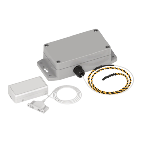
- Page 1 Radio Bridge ® LoRaWAN Wireless Sensor Water Detect Sensor User Guide...
- Page 2 Multi-Tech Systems, Inc. All rights reserved. Copyright © 2023 by Multi-Tech Systems, Inc. Trademarks and Registered Trademarks MultiTech, the MultiTech logo, DeviceHQ, and Conduit are registered trademarks of Multi-Tech Systems, Inc. All other products and technologies are the trademarks or registered trademarks of their respective holders.
-
Page 3: Table Of Contents
CONTENTS Contents Chapter 1 – Overview .............................. 5 Sensor Overview ................................5 Part Number.................................. 5 Documentation ................................6 Chapter 2 – Quick Start............................7 Preparing an RBS301 Sensor............................7 Preparing an RBS306 Sensor............................7 Quick Start..................................7 Installing Probe Water Sensors............................. 8 Installing Rope Water Sensors ............................ - Page 4 CONTENTS Chapter 6 – Safety ..............................25 Lithium Battery Safety ..............................25 User Responsibility..............................25 Chapter 7 – Regulatory Information........................26 Federal Communications Commission (FCC) ......................26 Harmonized Commodity Description (HS Code)......................26 Export Control Classification Number (ECCN)......................26 Index..................................27 ®...
-
Page 5: Chapter 1 - Overview
The LoRaWAN Wireless Water Detect Sensor uses a sensor probe to detect the presence of water or other liquids. When it detects water or another liquid, it sends an alert over the wireless network. Part Number Part Number Rating Wireless Region Water Probes RBS301-WAT-US Indoor LoRaWAN North America RBS306-WAT-US Outdoor/Industrial LoRaWAN North America Water Ropes –... -
Page 6: Documentation
OVERVIEW Documentation The following documentation is available at https://www.multitech.com/brands/reveal-wireless-leak-detection- sensors. Document Description Part Number User Guide This document provides overview, safety and regulatory RB00009 information, design considerations, schematics, and general hardware information. Connection Guide This document provides instructions and information on how... -
Page 7: Chapter 2 - Quick Start
Use your sensor through either the console or a third-party network. To use the console, use the following steps. To use a third-party network, refer to the Connecting LoRaWAN Sensors on Gateways and Networks (RB00001) , which is available through the sensor page at https://www.multitech.com/products/sensors Create a console account at: https://console.radiobridge.com/ Click on Devices on the left. -
Page 8: Installing Probe Water Sensors
QUICK START Note: For easy Device ID and Key entry, scan the QR code on the yellow key card included with your device. Then copy and paste data into the console. With the QR code, the first line is the Device ID and the rest is the key. -
Page 9: Installing Rope Water Sensors
QUICK START Installing Rope Water Sensors Rope water sensors detect leaks along the length of the rope, it can be wrapped around a fixture or spread across a room, dropped ceiling, or anywhere you need leak detection. Install the sensor so the rope reaches the area you want to monitor for water leaks. -
Page 10: Chapter 3 - Hardware Specifications And Information
Refer to the Sensor Battery Estimator.xlsx spreadsheet on the on the sensor's product page for specific battery life estimates: https://www.multitech.com/products/sensors Battery life depends on the number of transmissions per day. Power required for a message transmission is greater than the “sleep current” for high power radio technologies (e.g, LoRaWAN). - Page 11 HARDWARE SPECIFICATIONS AND INFORMATION Remove the battery. Insert the new battery as shown. Close the case. ® Radio Bridge LoRaWAN Wireless Sensor Water Detect Sensor User Guide...
-
Page 12: Mechanical Drawings
HARDWARE SPECIFICATIONS AND INFORMATION Mechanical Drawings The mechanical drawings provided in this section are for the main body of the sensor. All dimensions use inches unless specified. Indoor RBSx01 Sensors ® Radio Bridge LoRaWAN Wireless Sensor Water Detect Sensor User Guide... -
Page 13: Armored Outdoor/Industrial Rbsx06 Sensors
HARDWARE SPECIFICATIONS AND INFORMATION Armored Outdoor/Industrial RBSx06 Sensors ® Radio Bridge LoRaWAN Wireless Sensor Water Detect Sensor User Guide... -
Page 14: Chapter 4 - Common Messages
Common Messages This chapter defines the protocol and message definitions common to all MultiTech wireless sensors. Common messages include basic error messages, tamper, supervisory, link quality, and downlink acknowledgments. Sensor specific messages are in the Sensor Specific Messages chapter. -
Page 15: Reset Message 0X00
COMMON MESSAGES Item Size Description Message Payload 0-7 bytes Each message type has between 0 and 8 bytes of payload data specific to the sensor. Refer to the following table for payload information. 0x00 5-byte Device has reset. The reset cause is represented in the 5-byte reset code payload. reset code 0x01... -
Page 16: Supervisory Message 0X01
COMMON MESSAGES Byte Description Minor number (8 bits) Format (bit == 1) 14:10 Major number (5 bits) Minor number (5 bits) Build number (5 bits) 16-Bit Firmware Version Examples 0x0103 is decoded as Firmware Version 1.3 0x8823 is decoded as Firmware Version 2.1.3 Supervisory Message 0x01 Wireless sensors periodically (19 hours by default) send a supervisory message so the backend system can verify the device is still alive and report error conditions. -
Page 17: Tamper Message 0X02
COMMON MESSAGES Event accumulation count is the number of sensor events since the last supervisory message. To improve battery life, can be used with the Disable all sensor events setting so only an event total is reported during a supervisory message, individual events are not reported as they occur. This feature is available in firmware v2.0 and beyond. -
Page 18: General Configuration
COMMON MESSAGES General Configuration Use the general configuration command to configure parameters that apply to all sensor types. Byte Description 0x00 Disable sensor events 0x01 Radio config 0x02 Supervisory period. Default 19 hours. 0x03 Sampling rate ® Radio Bridge LoRaWAN Wireless Sensor Water Detect Sensor User Guide... - Page 19 COMMON MESSAGES Disable Sensor Events The following table shows the disable sensor event bit definitions. Description Not used Disable all sensor events Radio Config The following table shows the radio config byte definition. Note: Available in firmware version 1.4 or newer. Bits Description Not used (reserved)
- Page 20 COMMON MESSAGES Refer to the Battery Estimator for battery life estimates relative to sampling rate: https://radiobridge.com/documents/Sensor%20Battery%20Estimator.xlsx A value of 0 in this field leaves the sampling rate at the current value. Use the following table to determine the sampling rate if the value is not zero. Note: Sampling period only applies to sensors that take measurements like temperature and tilt, it does not apply to sensors with binary inputs such as door/window sensors or push buttons.
-
Page 21: Device Info Request
COMMON MESSAGES Device Info Request The Device Info Request command is a downlink to inform the gateway to report its downlink configuration information. Description 0x00 Downlink configuration type to request. 0-254: Request device info for specific downlink type to report. 255: Request device info for all downlink configurations. -
Page 22: Adr Advanced Configuration
COMMON MESSAGES ADR Advanced Configuration The ADR configuration message overrides the LoRaWAN ADR_ACK_LIMIT and ADR_ACK_DELAY parameters. Byte Description 0x00 ADR_ACK_LIMIT value when running in Unconfirmed Mode. The default value is 64. 0x01 ADR_ACK_DELAY value when running in Unconfirmed Mode. The default value is 32. 0x02 ADR_ACK_LIMIT value when running in Confirmed Mode. -
Page 23: Downlink Ack
COMMON MESSAGES Downlink ACK The cloud app uses this downlink ACK message to verify the that sensor received the downlink message received and it was considered valid. The sensor replies to the downlink data with a 0xFF message (downlink ACK) with the payload shown in the following table. -
Page 24: Chapter 5 - Sensor-Specific Messages
SENSOR-SPECIFIC MESSAGES Chapter 5 – Sensor-Specific Messages Uplink Messages The following table shows sensor specific uplink messages (sensor to web application). Uplink messages common to all sensors are in the previous chapter.. Byte Description Water event Bits Description Unused Water or liquid not present Water or liquid present Relative measurement of the resistance between probes (scale of 0-255). -
Page 25: Chapter 6 - Safety
Lithium cells and batteries are subject to the Provisions for International Transportation. Multi-Tech Systems, Inc. confirms that the Lithium batteries used in the MultiTech product(s) referenced in this manual comply with Special Provision 188 of the UN Model Regulations, Special Provision A45 of the ICAO-TI/IATA[1]DGR (Air), Special Provision 310 of the IMDG Code, and Special Provision 188 of the ADR and RID (Road and Rail Europe). -
Page 26: Chapter 7 - Regulatory Information
(1) This device may not cause harmful interference, and (2) this device must accept any interference received, including interference that may cause undesired operation. Per FCC 15.21, Changes or modifications not expressly approved by MultiTech could void authority to operate the devices. -
Page 27: Index
INDEX Index absolute maximum ratings ...........10 factory reset..............14 adaptive data rate............19 FCC part 15..............26 ADR................19 firmware version ............15 advanced configuration ...........22 advanced configuration ..........22 Armored Outdoor/Industrial Sensor......13 general configuration............18 battery remove tab..............7 install................8 9 replacement.............10 battery level ..............16 battery safety ..............25 ling quality message............17 link quality check period ..........22 link quality configuration ..........21... - Page 28 INDEX radio config ..............19 tamper message............17 RBSx06 Sensor...............13 temperature..............10 register sensor in console ..........7 regulatory..............26 replace................10 reset ................14 unconfirmed messages ..........19 reset message ...............15 uplink rope .................9 retries...............19 uplinke messages sensor specific............24 uplink messages safety................25 common ..............14 sampling rate ..............19 user responsibility............25 sensor event disable..............19...
Need help?
Do you have a question about the RBS301-WAT-US and is the answer not in the manual?
Questions and answers