Table of Contents
Advertisement
Quick Links
Advertisement
Table of Contents

Related Manuals for Multitech REVEAL RBS301-VOLT


Summary of Contents for Multitech REVEAL RBS301-VOLT
- Page 1 Reveal™ Wireless Voltage Sensor User Guide...
- Page 2 Trademarks and Registered Trademarks MultiTech, the MultiTech logo, DeviceHQ, xDot, and Conduit are registered trademarks and Reveal and mDot are trademarks of Multi-Tech Systems, Inc. All other products and technologies are the trademarks or registered trademarks of their respective holders.
-
Page 3: Table Of Contents
CONTENTS Contents Chapter 1 – Quick Start............................4 Overview ..................................4 Part Numbers ................................4 Documentation ................................4 Chapter 2 – Preparing Sensor........................... 5 Preparing an RBS301 Sensor............................5 Preparing an RBS306 Sensor............................5 Quick Start..................................5 Chapter 3 – Hardware Specifications and Information ..................... 7 Absolute Maximum Ratings ............................ -
Page 4: Chapter 1 - Quick Start
Outdoor/Industrial LoRaWAN North America, South America RBS306-VM30-EU Outdoor/Industrial LoRaWAN Europe Documentation The following documentation is available at https://www.multitech.com/products/sensors. Document Description Part Number User Guide This document provides overview, safety and regulatory RB00016 information, design considerations, schematics, and general hardware information. -
Page 5: Chapter 2 - Preparing Sensor
Console, use the following steps. To use a third-party network, refer to the Connecting Radio Bridge LoRaWAN Sensors on Gateways and Networks (RB00001) , which is available through the sensor page at https://www.multitech.com/products/sensors Create a Radio Bridge console account at: https://console.radiobridge.com/... - Page 6 PREPARING SENSOR Note: For easy Device ID and Key entry, scan the QR code on the device label. Then copy and paste data into the console. With the QR code, the first line is the Device ID and the rest is the key. Select the model from the Device Type drop down.
-
Page 7: Chapter 3 - Hardware Specifications And Information
Refer to the Sensor Battery Estimator.xlsx spreadsheet on the on the sensor's product page for specific battery life estimates: https://www.multitech.com/products/sensors Battery life depends on the number of transmissions per day. Power required for a message transmission is greater than the “sleep current” for high power radio technologies (e.g, LoRaWAN). -
Page 8: Mechanical Drawings
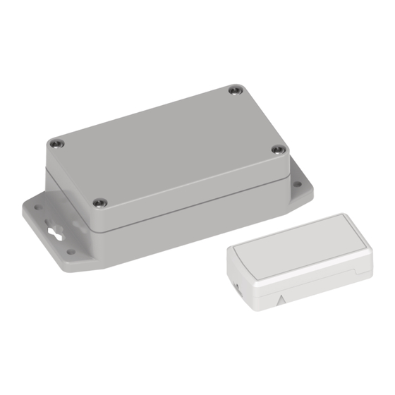
HARDWARE SPECIFICATIONS AND INFORMATION Mechanical Drawings The mechanical drawings provided in this section are for the main body of the sensor. All dimensions use inches unless specified. Indoor RBSx01 Sensors Reveal™ Wireless Voltage Sensor User Guide... -
Page 9: Armored Outdoor/Industrial Rbsx06 Sensors
HARDWARE SPECIFICATIONS AND INFORMATION Armored Outdoor/Industrial RBSx06 Sensors Reveal™ Wireless Voltage Sensor User Guide... -
Page 10: Chapter 4 - Common Messages
Sensor Specific Messages chapter. Message Protocol This section defines the protocol and message definitions for the device. Note: MultiTech provides a web-based console at console.radiobridge.com for configuring and monitoring devices. We recommend using this console rather than the protocols defined in this section. -
Page 11: Reset Message 0X00
COMMON MESSAGES Message Payload Description 0xfb Link quality Sent after each downlink configuration (refer to Link Quality Message) or to periodically ping the network server (refer to Link Quality Check Period). 0xfe Reserved. 0xff 1-byte status Downlink message ACK. Refer to Downlink ACK for more detail. -
Page 12: Supervisory Message 0X01
COMMON MESSAGES Supervisory Message 0x01 Wireless sensors periodically send a supervisory message so the backend system can verify the device is still alive and report error conditions. The supervisory message payload include current sensor status. You can also trigger a supervisory message. To do this: Place a magnet near the triangular notch on the side of the sensor. -
Page 13: Downlink Messages
COMMON MESSAGES Bytes Description Current Sub-Band, sub-band currently joined and used for communication to the gateway and network server. Value ranges from 1-8 for US915. For other regions, value depends on available channels. RSSI of last DOWNLINK received, signed integer format values in bytes 1 and 2 in two’s complement format. - Page 14 COMMON MESSAGES Radio Config The following table shows the radio config byte definition. Note: Available in firmware version 1.4 or newer. Bits Description Not used (reserved) Enable duty cycle requirement. LoRaWAN EU868 only. To enforce the EU868 band duty cycle requirements, enable before production deployment.
-
Page 15: Advanced Configuration
COMMON MESSAGES Bit 7:6 Bits 5:0 Sampling period defined in increments of 250ms (0.25-15 seconds). Sampling period defined in increments of seconds (1-63 seconds). Sampling period defined in increments of minutes (1-63 minutes). Sampling period defined in increments of hours (1-63 hours). Advanced Configuration Use this command for advanced configuration parameters that apply to all sensor types. -
Page 16: Downlink Ack
COMMON MESSAGES Downlink ACK The cloud app uses this downlink ACK message to verify the that sensor received the downlink message received and it was considered valid. The sensor replies to the downlink data with a 0xFF message (downlink ACK) with the payload shown in the following table. -
Page 17: Chapter 5 - Sensor-Specific Messages
SENSOR-SPECIFIC MESSAGES Chapter 5 – Sensor-Specific Messages Uplink Messages The uplink message (sensor to web application) specific to the sensor is defined in following table. The common uplink messages are not included in this section (see common messages document). Bytes Description Voltage Measurement Event Payload (see Voltage Measurement Event Payload Definitions) -
Page 18: Report On Change Mode
SENSOR-SPECIFIC MESSAGES Byte Description Periodic reporting in 1 minute or 1 hour intervals. Default is 0 (disabled) Restoral margin. Default is 100mV. Lower analog measurement threshold. Default 10V. Upper analog measurement threshold. Default 12V. The upper and lower thresholds are unsigned values with units of 10mV. Note that if the configuration settings exceed the maximum ratings on the sensor, the sensor may not report an event. - Page 19 SENSOR-SPECIFIC MESSAGES Bit 7 Bits 6:0 Period defined in hours (1-127 hours) Period defined in minutes (1-127 minutes) For example, to receive a report every 4 hours, byte 1 would be set to 0x04. To receive a periodic report every 15 minutes, byte 1 would be set to 0x8f.
-
Page 20: Chapter 6 - Regulatory Information
(1) This device may not cause harmful interference, and (2) this device must accept any interference received, including interference that may cause undesired operation. Per FCC 15.21, Changes or modifications not expressly approved by MultiTech could void authority to operate the devices.
Need help?
Do you have a question about the REVEAL RBS301-VOLT and is the answer not in the manual?
Questions and answers