Table of Contents
Advertisement
Quick Links
Advertisement
Table of Contents

Related Manuals for Multitech RBS301-TILT-US


Summary of Contents for Multitech RBS301-TILT-US
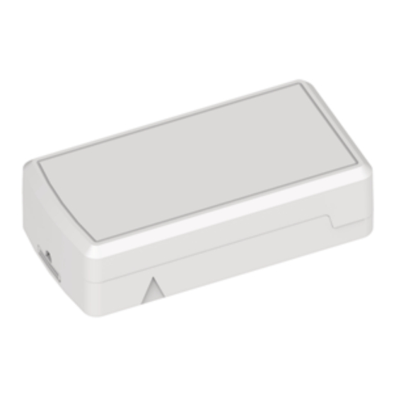
- Page 1 Radio Bridge ® LoRaWAN Wireless Sensor Tilt Sensor User Guide...
- Page 2 Multi-Tech Systems, Inc. All rights reserved. Copyright © 2023 by Multi-Tech Systems, Inc. Trademarks and Registered Trademarks MultiTech, the MultiTech logo, DeviceHQ, and Conduit are registered trademarks of Multi-Tech Systems, Inc. All other products and technologies are the trademarks or registered trademarks of their respective holders.
-
Page 3: Table Of Contents
CONTENTS Contents Chapter 1 – Quick Start............................5 Overview ..................................5 Part Numbers ................................5 Documentation ................................5 Chapter 2 – Preparing Sensor........................... 6 Preparing an RBS301 Sensor............................6 Quick Start..................................6 Mounting the Sensor ..............................7 Mounting the Sensor with the Tamper Screw......................7 Chapter 3 –... - Page 4 CONTENTS Control Byte ................................21 Chapter 6 – Safety ..............................22 Lithium Battery Safety ..............................22 User Responsibility..............................22 Chapter 7 – Regulatory Information........................23 Federal Communications Commission (FCC) ......................23 Harmonized Commodity Description (HS Code)......................23 Export Control Classification Number (ECCN)......................23 ®...
-
Page 5: Chapter 1 - Quick Start
When the sensor is rotated from horizontal to vertical or vice versa, an alert is sent to the wireless network. The thresholds for triggering a tilt event are configurable over the air. Part Numbers Part Number Rating Wireless Region RBS301-TILT-US Indoor LoRaWAN North America Documentation The following documentation is available at https://www.multitech.com/brands/reveal-wireless-movement- sensors. -
Page 6: Chapter 2 - Preparing Sensor
Use your sensor through either the console or a third-party network. To use the console, use the following steps. To use a third-party network, refer to the Connecting LoRaWAN Sensors on Gateways and Networks (RB00001) , which is available through the sensor page at https://www.multitech.com/products/sensors Create a console account at: https://console.radiobridge.com/ Click on Devices on the left. -
Page 7: Mounting The Sensor
PREPARING SENSOR Mounting the Sensor To mount the sensor: Use the large adhesive pad included with a sensor to secure the case in position. Mounting the Sensor with the Tamper Screw For increased security, open the case, and fasten it to the wall using the included tamper screw as shown. Then reassemble the case. -
Page 8: Chapter 3 - Hardware Specifications And Information
Refer to the Sensor Battery Estimator.xlsx spreadsheet on the on the sensor's product page for specific battery life estimates: https://www.multitech.com/products/sensors Battery life depends on the number of transmissions per day. Power required for a message transmission is greater than the “sleep current” for high power radio technologies (e.g, LoRaWAN). - Page 9 HARDWARE SPECIFICATIONS AND INFORMATION Remove the battery. Insert the new battery as shown. Close the case. ® Radio Bridge LoRaWAN Wireless Sensor Tilt Sensor User Guide...
-
Page 10: Mechanical Drawings
HARDWARE SPECIFICATIONS AND INFORMATION Mechanical Drawings The mechanical drawings provided in this section are for the main body of the sensor. All dimensions use inches unless specified. Indoor RBSx01 Sensors ® Radio Bridge LoRaWAN Wireless Sensor Tilt Sensor User Guide... -
Page 11: Chapter 4 - Common Messages
Chapter 4 – Common Messages Common Messages This chapter defines the protocol and message definitions common to all MultiTech wireless sensors. Common messages include basic error messages, tamper, supervisory, link quality, and downlink acknowledgments. Sensor specific messages are in the Sensor Specific Messages chapter. -
Page 12: Reset Message 0X00
COMMON MESSAGES Message Type Payload Description 0x02 1-byte event A tamper event has occurred. Refer to Tamper Message 0x02for details. Sensor event Sensor events are defined in the Sensor Specific Messages chapter. 0xfb Link quality Sent after each downlink configuration (refer to Link Quality Message) or to periodically ping the network server (refer to Link Quality Check... -
Page 13: Supervisory Message 0X01
COMMON MESSAGES 0x8823 is decoded as Firmware Version 2.1.3 Supervisory Message 0x01 Wireless sensors periodically (19 hours by default) send a supervisory message so the backend system can verify the device is still alive and report error conditions. The supervisory message payload include current sensor status. You can also trigger a supervisory message. -
Page 14: Link Quality Message 0Xfb
COMMON MESSAGES Link Quality Message 0xfb The link quality message provides a signal strength and a signal to noise measurement at the device itself. The link quality message payload is shown in the following table. Bytes Description Current Sub-Band, sub-band currently joined and used for communication to the gateway and network server. - Page 15 COMMON MESSAGES Disable Sensor Events The following table shows the disable sensor event bit definitions. Description Not used Disable all sensor events Radio Config The following table shows the radio config byte definition. Note: Available in firmware version 1.4 or newer. Bits Description Not used (reserved)
- Page 16 COMMON MESSAGES Refer to the Battery Estimator for battery life estimates relative to sampling rate: https://radiobridge.com/documents/Sensor%20Battery%20Estimator.xlsx A value of 0 in this field leaves the sampling rate at the current value. Use the following table to determine the sampling rate if the value is not zero. Note: Sampling period only applies to sensors that take measurements like temperature and tilt, it does not apply to sensors with binary inputs such as door/window sensors or push buttons.
-
Page 17: Device Info Request
COMMON MESSAGES Device Info Request The Device Info Request command is a downlink to inform the gateway to report its downlink configuration information. Description 0x00 Downlink configuration type to request. 0-254: Request device info for specific downlink type to report. 255: Request device info for all downlink configurations. -
Page 18: Adr Advanced Configuration
COMMON MESSAGES ADR Advanced Configuration The ADR configuration message overrides the LoRaWAN ADR_ACK_LIMIT and ADR_ACK_DELAY parameters. Byte Description 0x00 ADR_ACK_LIMIT value when running in Unconfirmed Mode. The default value is 64. 0x01 ADR_ACK_DELAY value when running in Unconfirmed Mode. The default value is 32. 0x02 ADR_ACK_LIMIT value when running in Confirmed Mode. -
Page 19: Downlink Ack
COMMON MESSAGES Downlink ACK The cloud app uses this downlink ACK message to verify the that sensor received the downlink message received and it was considered valid. The sensor replies to the downlink data with a 0xFF message (downlink ACK) with the payload shown in the following table. -
Page 20: Chapter 5 - Sensor-Specific Messages
SENSOR-SPECIFIC MESSAGES Chapter 5 – Sensor-Specific Messages Uplink Messages The uplink message (sensor to web application) specific to the sensor is defined in following table. The common uplink messages are not included in this section (see common messages document). Byte Description 0x00 Tilt event... -
Page 21: Thresholds
SENSOR-SPECIFIC MESSAGES Thresholds The angle in bytes 1 and 2 define the angle in degrees off of the vertical axis that the sensor needs to be tilted to generate an alert. For example, if the sensor is used to detect garage open/close events, the vertical threshold might be set at 35 degrees and the horizontal threshold may be set at 55 degrees. -
Page 22: Chapter 6 - Safety
Lithium cells and batteries are subject to the Provisions for International Transportation. Multi-Tech Systems, Inc. confirms that the Lithium batteries used in the MultiTech product(s) referenced in this manual comply with Special Provision 188 of the UN Model Regulations, Special Provision A45 of the ICAO-TI/IATA[1]DGR (Air), Special Provision 310 of the IMDG Code, and Special Provision 188 of the ADR and RID (Road and Rail Europe). -
Page 23: Chapter 7 - Regulatory Information
(1) This device may not cause harmful interference, and (2) this device must accept any interference received, including interference that may cause undesired operation. Per FCC 15.21, Changes or modifications not expressly approved by MultiTech could void authority to operate the devices.
Need help?
Do you have a question about the RBS301-TILT-US and is the answer not in the manual?
Questions and answers