
Related Manuals for THORLABS PM101


Summary of Contents for THORLABS PM101
- Page 1 Optical Power Meter Interfaces PM101, PM101A, PM101R, PM101U Operation Manual 2019...
- Page 2 Version: Date: 13-Aug-2019 Copyright © 2019 Thorlabs...
-
Page 3: Table Of Contents
3.2.15 NTC Input 3.2.16 Power Supply 3.3 Software 3.3.1 Software Requirements 3.3.2 PM101x Specific Software Functions 3.3.2.1 PM101 Specific Software Functions 3.3.2.2 PM101A Specific Software Functions 3.4 Maintenance and Service 4 Appendix 4.1 Technical Data 4.2 Pin Assignment Output Connector... - Page 4 4.3 Pin Assignment of the Sensor Connector 4.4 Safety 4.5 Return of Devices 4.6 Certifications and Compliances 4.7 Warranty 4.8 Copyright and Exclusion of Reliability 4.9 Thorlabs Worldwide Contacts - WEEE Policy...
- Page 5 Paragraphs preceded by this symbol explain hazards that could damage the instrument and the connected equipment or may cause loss of data. Note This manual also contains "NOTES" and "HINTS" written in this form. Please read this advice carefully! © 2019 Thorlabs...
-
Page 6: General Information
For the PM101U and PM101A power meters, instrument control and power supply are facilita- ted via the USB port. The PM101R can be controlled via the DE-9 port. The PM101 can alter- natively use the DA-15 interface for instrument control and to connect a power supply. For... -
Page 7: Pm101X Model Comparison
Ö Autonomous Operation to Ö Ö Analog Output Real Analog Output Ö Sensitivity Configurable Ö Ö Analog Output UART Operation Ö 2 Auxiliary I/O ports Ö NTC Input Ö Power Supply +5V to +36V Ö Table 1 © 2019 Thorlabs... -
Page 8: Ordering Codes And Accessories
Thorlabs offers a variety of SMA connector cables. · PM101: Cable to attach to the provided DA-15 connector housing. Mounting · Horizontal Mounting Clamp (ECM225) to mount the PM101x onto a post. · Vertical Mounting Clamp (ECM100) to mount the narrow side of the PM101x onto a post. -
Page 9: Requirements
PM101A: Please provide an appropriate cable to connect to the SMA port. Software Requirements All models of the PM101x can be run with the Thorlabs' OPM software. Please see the require- ments for the OPM on the website. Sensor Requirements Thorlabs C-Series Sensors The PM101x supports all Thorlabs C-Series photodiode and thermal sensors. -
Page 10: Getting Started
1. PM101x Optical Power Meter Interface 2. USB Cable, Type A to Mini B, with Locking Screw, 1.5 m 3. PM101R: RS232 cable, DE-9 Male to DE-9 Female, 1.8 m 4. PM101: DA-15 Connector and Connector Housing 5. Quick Reference 6. Certificate of Calibration... -
Page 11: Operating Instructions
· Connect the PM101x to a PC or other power source via the USB port. o The PM101 accepts external power supplies with 5 V to 36 V via the DA-15 interface. When connecting the USB port while using an external power supply via the DA-15 port, connecting the USB port will automatically switch to the 5 V power supply via USB. - Page 12 DE-9 connectors. Note Custom Sensors To use sensors without a DE-9 connector, manufactured by Thorlabs or else, the user may provide an appropriate adapter. To build the adapter, refer to the Pin-out of the DE-9 connector shown in the Appendix .
-
Page 13: Power Meter Interface Features
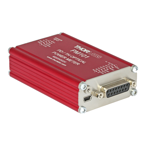
, described in the following chapters. 3.2.1 PM101x Sensor Connector All models of the PM101x have the same connector shown here to the left side. The Pin as- signment is engraved on the front of the PM101x. © 2019 Thorlabs... -
Page 14: Pm101
The PM101 features a number of additional options, due to the DA-15 output connector. The PM101 is per default configured to RS232 configuration (+/- 5 V voltage level). This can be changed to a UART configuration (0/5 V voltage level) so that the PM101 can be accessed by external micro-controllers for instrument control and data export. -
Page 15: Pm101A
3 Operating Instructions 3.2.3 PM101A PM101A Special Features Autonomous Operation to analog output. Configurable Analog Output 3. Power Meter Control and Output via USB © 2019 Thorlabs... -
Page 16: Pm101R
3. Instrument Control using SCPI commands (RS232 Serial Communication). Please see the document PM101x-WYOA for details. 4. Power Meter Control and Output via USB 3.2.5 PM101U PM101U Special Features · Power Meter Control and Output via USB © 2019 Thorlabs... -
Page 17: Usb Operation
Termination Character LF (x0A; \n). The termination character needs to be enabled. Note PM101: To operate the PM101 via RS232, RxD, TxD, and GND need to be wired from the DA-15 con- nector to a 9 Pin female connector to perform the connections. PM101 DA-15 Pin... -
Page 18: Uart Operation
PM101 control. In RS232 operation the PM101 uses voltage levels of +/-5 V, while in UART mode the voltage level is shifted to 0/5 V. The PM101 can also be adjusted to accommodate micro-controllers using 3.3 V. When switched to 3.3 V, UART operation is toler- ant for 5 V input signal. -
Page 19: Analog Output
Power meters PM101 and PM101A can be run autonomously by only connecting a power sup- ply and using analog output. In that case, no control device is required. For the PM101, both analog output ports can be used for autonomous operation. -
Page 20: Ntc Input
PM101x 3.2.15 NTC Input To monitor the temperature in a test environment, the PM101 has an NTC Input (DA-15 Pin 14) which allows connection of an NTC thermistor. The measurement range is 0.1 – 100 kW. The set range R0 and the bandwidth B for the NTC thermistor can be adjusted in the OPM software or through SCPI commands. -
Page 21: Software Requirements
NTC measurements results in long-time monitoring experiments. For more information, please see the OPM manual. 2. When a PM101 is connected, it is possible to configure the analog AO2 port and display the output voltage. 3.3.2.2 PM101A Specific Software Functions When a PM101A is connected, it is possible to configure the analog SMA port and display the output voltage. -
Page 22: Appendix
Sensor Dependent; nm, (V/W) Beam Area Setting Diameter 1/e² or Rectangular x,y Sensor Temperature Control Supported Temperature Sensor Thermistor Temperature Measurement -10° C to 120° C Range Sensor Power Supply Connector DE-9 Pin 1 Voltage 100 mA Maximum Current © 2019 Thorlabs... - Page 23 Power Management +5 VDC to +36 DC Input 1 / Connector VDC / DA-15 DC Input 2 / Connector 5 V / USB Power Consumption Display Display Type None; External PC - Windows Application or Driver Set © 2019 Thorlabs...
- Page 24 1.00" 1.00" Dimensions (L x W x H) (96.5 x 57.2 x (100.0 x 57.2 x (95.9 x 57.2 x (93.6 x 57.2 x 25.4 mm 25.4 mm 25.4 mm 25.4 mm Weight 0.16 kg (0.35 lb) © 2019 Thorlabs...
-
Page 25: Pin Assignment Output Connector
Not Connected N.C. Not Connected N.C. Not Connected PM101: PM101 has a universal DA-15 connector. The Pins are assigned as follows: Pin Function Description Power Supply Pin for Alternative Power Supply with 5 VDC to 36 VDC I/O 1 General Digital Input / Output port; 3 V logic (Output), 5 V tolerant for In- I/O 2 General Digital Input / Output port;... -
Page 26: Pin Assignment Of The Sensor Connector
Warning Pin 2 is uniquely used for the EEPROM Digital I/O (memory in Thorlabs sensor heads) and MUST NOT be used. Connecting this Pin may cause malfunction of the PM101x. Pin-out of the DE-9 female... -
Page 27: Return Of Devices
Thorlabs GmbH. The correction of interference caused by such unau- thorized modification, substitution or attachment will be the responsibility of the user. -
Page 28: Certifications And Compliances
PM101x 4.6 Certifications and Compliances © 2019 Thorlabs... -
Page 29: Warranty
Thorlabs warrants material and production of the PM101x for a period of 24 months starting with the date of shipment. During this warranty period Thorlabs will see to defaults by repair or by exchange if these are entitled to warranty. -
Page 30: Thorlabs Worldwide Contacts - Weee Policy
Contact Thorlabs for more information. Waste treat- ment is your own responsibility. “End of life” units must be returned to Thorlabs or handed to a company specializing in waste recovery. Do not dispose of the unit in a litter bin or at a public waste disposal site. - Page 31 www.thorlabs.com...
Need help?
Do you have a question about the PM101 and is the answer not in the manual?
Questions and answers