
Subscribe to Our Youtube Channel
Related Manuals for Raymarine DSM25


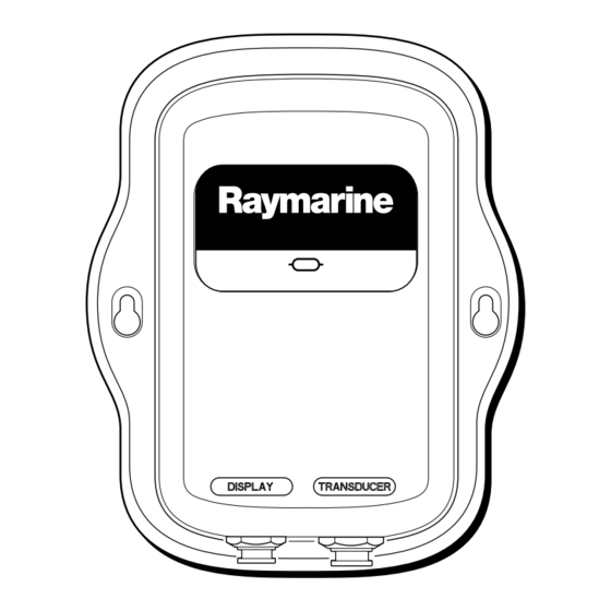
Summary of Contents for Raymarine DSM25
- Page 1 DSM25 Digital Sounder Module Owner’s Handbook Document number: 81254-2 Date: March 2006...
-
Page 2: Trademarks And Registered Trademarks
Trademarks and registered trademarks Raymarine is a registered trademark of Raymarine plc. All other product names are trademarks or registered trademarks of their respective owners. Contents of this handbook © Raymarine 2006. -
Page 3: Table Of Contents
Interpreting the Bottom Structure ... 13 How Targets are Displayed ... 14 1.4 How to Use this Handbook ... 15 Chapter 2: DSM25 Installation ...17 2.1 Introduction ... 17 Planning the Installation ... 17 2.2 Unpacking and Inspecting the Components ... 17 2.3 Optional Equipment ... - Page 4 4.2 Fishfinder Alarms ...46 Target Depth ID ...46 Fish Alarm ...47 Fish Sensitivity ...47 Shallow Alarm ...47 Shallow Range ...47 Deep Alarm ...47 Deep Range ...47 Temp. Alarm ...47 Temp. Range High ...48 Temp. Range Low ...48 DSM25 Owner’s Handbook...
- Page 5 Factory Reset ... 51 5.3 Problem Solving ... 52 Common Problems and Their Solutions ... 52 Status LED ... 53 5.4 How to Contact Raymarine ... 54 On the Internet ... 54 In the US ... 55 In Europe ... 56 Worldwide Support ...
- Page 6 DSM25 Owner’s Handbook...
-
Page 7: Important Information
DSM25 can also display temperature, distance traveled, and/or speed. This manual contains important information for installing and operating your DSM25. To get the best results in operation and performance, please take the time to read this handbook thoroughly. Raymarine’s Technical Services representatives or your local dealer will be available to answer any questions you may have. -
Page 8: Emc Conformance
If the transducer cable is accidentally removed while the DSM25 is powered on, remove power from the sounder module, replace the transducer cable, and then return power to the module. As a safety feature, the DSM25 only recognizes that the transducer is connected at power-up. -
Page 9: Suppression Ferrites
The following illustration shows typical cable suppression ferrites sometimes used with Raymarine equipment. To ensure EMC compliance, always use these ferrites, if supplied by Raymarine for use with this equipment. If not supplied by Raymarine, a ferrite is not required for use with this equipment. -
Page 10: Conventions
Technical Accuracy The technical and graphical information contained in this handbook, to the best of our knowledge, was correct as it went to press. However, the Raymarine policy of continuous improvement and updating may change product specifications without prior notice. As a result, unavoidable differences between the product and handbook may occur from time to time. -
Page 11: Chapter 1: Overview
This handbook describes how to install the DSM25 Digital Sounder Module and operate it using the A65 display unit. The DSM25 emits and receives sonar signals from a transducer mounted in the water, then interprets and transmits the data to the A65 installed on the console. -
Page 12: What The Sounder Displays
1.2 What the Sounder Displays When you first view the Fishfinder application on the A65, an image representing the echoes received by the DSM is displayed. As time passes this image scrolls from right to left and becomes a record of the data collected. The images at the right hand side of the display are therefore the most recent. -
Page 13: How The Fishfinder Works
Chapter 1: Overview 1.3 How the Fishfinder Works The Fishfinder application uses the DSM25 to process sonar signals from a suitable transducer and provide a detailed underwater view. The transducer located on the bottom of the boat sends pulses of sound waves into the water and measures the time it takes for the sound wave to travel to the bottom and back. -
Page 14: How Targets Are Displayed
ID in the Fishfinder Alarms Setup Menu. The size of the target The larger the target, the larger the return on the fishfinder display. The size of a fish target is however dependent upon the size of the fish’s swim bladder rather than its overall size. -
Page 15: How To Use This Handbook
You can however adjust these settings manually if you prefer. 1.4 How to Use this Handbook This handbook describes how to install and operate a DSM25 with your A65 display unit. Chapter 2 provides planning considerations and detailed instructions for installing the DSM25 and connecting the sounder module to the display unit. - Page 16 DSM25 Owner’s Handbook RS12 GPS DSM25 A65 Display Power Supply D7746-1 Transducer...
-
Page 17: Chapter 2: Dsm25 Installation
Chapter 2: DSM25 Installation 2.1 Introduction This chapter provides details for mounting the DSM25 and connecting to the A65 display. For the system to display depth, water temperature and speed, you must install the transducer type(s) capable of transmitting the appropriate data. -
Page 18: Optional Equipment
A65 Network Cable, 8.5m A65 Network Cable 15m 2.4 Selecting Sounder Module Mounting Location The DSM25 is waterproof to IPX-7 is and is designed to be mounted either above or below deck. Mount the DSM25 where it is: • protected from physical damage and excessive vibration •... -
Page 19: Mounting The Sounder Module
2.5 Mounting the Sounder Module The DSM25 can be mounted either above or below deck using the supplied hardware. To allow for ease of cable connection, mount the sounder module so that the cables hang below the unit. - Page 20 Before drilling the pilot hole, hand drill the marked location with an oversized bit and countersink to approximately 3/8" (9mm) diameter. 4. Drive the supplied #8 screws into the pilot holes. Screw them in about half way. DSM25 Owner’s Handbook D7740-1 D7741-1...
-
Page 21: Cable Runs
2.6 Cable Runs You will need to run the following cables: • Data/power cable , supplied with the DSM25. This 11.5 ft (3.5 m) cable connects the sounder to the A65 display unit. Longer cables are also available (see “Optional Equipment” on page 18). -
Page 22: System Connections
The 8-pin connector labelled DISPLAY provides a connection for both power and data to the A65 display. There is no power switch on the DSM25. The unit turns on when the network cable is attached to an A65 display and the A65 is energized. -
Page 23: Chapter 3: Using The Sounder Module
Chapter 3: Using the Sounder Module 3.1 Introduction The standard fishfinder image is an historical, scrolling bottom graph at an automatically selected range and frequency. Various functions are provided to improve the underwater view, select what is displayed and sound an alarm including: •... -
Page 24: Selecting The Display Page
3.2 Selecting the Display Page Before viewing fishfinder functions, you must select the fishfinder page on the A65 display. The display provides you with different window configurations for presenting information. To change the display pages: 1. Press the PAGE key. The associated soft keys are displayed: CHART 2. - Page 25 Split windows displaying sounder and chart information 12nm Csr Pos FISHFINDER FISHFINDER SETTINGS SETTINGS • Fishfinder/Navigation Data Page Split windows displaying sounder and position data (via GPS), including cur- rent time, date, TTG, COG, range and bearing and depth information 50 kHz FISHFINDER FISHFINDER SETTINGS...
- Page 26 A-SCOPE ZOOM ZOOM LOCK LOCK >> 0.067 WPT BRG BOTTOM BOTTOM A-SCOPE A-SCOPE ZOOM ZOOM LOCK LOCK DSM25 Owner’s Handbook 71.5° Minutes 13.5 71.5°F 26°16.618 W 080°04.961 28.6ft 9:35:08am PRESENTATION PRESENTATION WPT 0003 STEER STARBOARD HEADING °T °T WPT RNG VMG (WPT) 0.42...
-
Page 27: Using The Course Deviation Indicator (Cdi)
Chapter 3: Using the Sounder Module Using the Course Deviation Indicator (CDI) With your display receiving accurate heading and position information, you can use the CDI to monitor your course and accurately steer to a target waypoint. The CDI gives a graphical representation of yours boat’s course in a ‘rolling road’ format. -
Page 28: Adjusting The Display
4. Use the rotary control to adjust the shift up or down. The value of the shift is displayed on the soft key. 5. To return to the standard fishfinder image, toggle the RANGE soft key to AUTO. The default range shift setting is 0. This setting is reset at power-up. -
Page 29: Soft Key Selections
Although you can also manually adjust these settings, Raymarine recommends that you retain the AUTO setting to achieve the best results. All of the GAIN settings are reset at power-on. -
Page 30: Auto Gain
This function is useful for reducing the appearance of ‘noise’. Increasing the TVG value increases the maximum depth to which TVG is applied. Decreasing it reduces the maximum depth. TVG has no effect in fishfinder Simulator Mode. -
Page 31: Operating Frequency
50 kHz to 200 kHz. This mode is useful for automatically searching for the bot- tom. This is the default setting. • 50 kHz only . The DSM25 scans a wide area and penetrates water well, so is good for use in deep water. -
Page 32: Power Settings
To change the frequency to a manual setting: 1. Press FISHFINDER SETTINGS. A new set of soft keys appear. 2. Press FREQUENCY until MAN is highlighted. The SELECTED FREQ soft key is no longer grayed out. 3. Toggle the SELECTED FREQ key until the desired setting is highlighted: •... -
Page 33: Zoom
ON SPLIT OFF x2 x3 x4 xR The DSM25 automatically keeps the bottom image in the lower half of the window. When you need to see more detail of the bottom structure or targets, you can zoom in and enlarge a portion of the image. This zoom range box can either replace or appear alongside the standard sounder image. -
Page 34: Adjusting The Position Of The Zoomed Area
If you have chosen the split screen option, the zoomed section is indicated on the standard fishfinder screen by a zoom box (see preceding illustration). 4. Press CANCEL or ENTER to return to the standard fishfinder soft keys. Adjusting the Position of the Zoomed Area 1. - Page 35 1. Press BOTTOM LOCK. The Bottom Lock soft keys are displayed. 2. Toggle to: • BOTTOM LOCK ON to replace the standard fishfinder image with the bot- tom lock image. • BOTTOM LOCK SPLIT to display both the standard fishfinder and bottom lock image in a single window.
-
Page 36: A-Scope
43 9 A-SCOPE A-SCOPE MODE A-SCOPE A-SCOPE MODE Note: If the Bottom Lock or Zoom image was displayed, selecting A-Scope automatically switches OFF Bottom Lock and Zoom. A-Scope MODE 1 DSM25 Owner’s Handbook MODE 2 14.2 14.2 MODE 3 14.2 D7912-1... -
Page 37: Presentation
Chapter 3: Using the Sounder Module 3.8 Presentation You can further adjust the fishfinder image using features accessed via the PRESENTATION soft keys: WHITE LINE VRM... White Line and Bottom Fill These two related features help better define images near the bottom. -
Page 38: White Line And Bottom Fill Together
DSM25 Owner’s Handbook White Line and Bottom Fill together When both White Line and Bottom Fill are applied, the bottom is defined by a white line and the detail below it replaced by a single contrasting color. Both the bottom and fish near the bottom are now clearly defined. -
Page 39: Scroll Pause/Resume
Fishfinder Setup menu. See • Depth Lines are horizontal dashed lines drawn at regular intervals to indi- cate the depth from the surface. These are switched on/off via the Fishfinder Setup menu. See page 43. • Target Depth ID displays the depths of recognized targets. These are switched on/off via the Fishfinder Alarms Setup menu, described on page 46. -
Page 40: Using Waypoints
5. Press ENTER twice to save the waypoint with the standard settings. For greater details of how to place a waypoint, please refer to the Waypoints chapter of the A65 User’s Handbook. BOTTOM BOTTOM ZOOM ZOOM LOCK LOCK DSM25 Owner’s Handbook A-SCOPE A-SCOPE PRESENTATION PRESENTATION... -
Page 41: Chapter 4: Fishfinder Setup
Chapter 4: Fishfinder Setup Fishfinder Setup functions can be accessed using the controls that are displayed when you press the MENU key on the A65 display. Note: All settings described in this chapter—except Max. Ping Rate and Ping Enable— are retained when the unit is powered off. - Page 42 8. Press CANCEL or ENTER twice to return to the default screen. Fishfinder Setup Fishfinder Setup LARGE CLASSIC/BLUE 0.0 ft 100% 0.0 F 26 Pings/Sec. ENABLED Fishfinder Setup Fishfinder Setup LARGE CLASSIC/BLUE 0.0 ft 100% 26 Pings/Sec. ENABLED DSM25 Owner’s Handbook...
-
Page 43: Dsm Setup
• ON Palette The DSM25 offers you six different display color combinations. You can select the color set for a bold or soft color palette. The brightness of the screen can be adjusted over a wide range, suitable for viewing in daylight (high brightness level) or at night (low brightness level). -
Page 44: Depth Offset
The default is 100%. Temp Calibrate If the transducer is equipped with a thermistor, the DSM25 calculates the temperature of the water. The temperature calibrate option enables you to adjust the displayed temperature. You can adjust the displayed temperature by –9.0°F to +9.0°F or –5.5°C to +5.5°C. -
Page 45: Interference Rejection (Int Rej)
Chapter 4: Fishfinder Setup Interference Rejection (Int Rej) Two or more sonar-equipped vessels operating within range of each other can interfere with sounder operation. This usually appears as vertical streaks on the display that do not represent actual targets. This option can reduce such interference, either manually or automatically. -
Page 46: Fishfinder Alarms
Target Depth ID Controls whether the depth of identified targets are displayed. The default setting is OFF. Setup Setup Alarms Setup Alarms Setup Alarms Setup Alarms Setup DSM25 Owner’s Handbook... -
Page 47: Fish Alarm
Chapter 4: Fishfinder Setup Fish Alarm If this alarm is ON, the unit sounds a beeper whenever it finds a fish. The default setting is OFF. Fish Sensitivity If the Fish Alarm is set ON, an alarm is triggered when the fish return strength reaches the sensitivity that you specify. -
Page 48: Temp. Range High
Use the rotary knob or trackpad up/down keys to increment/decrement the lower threshold for the Temp Alarm. If a temperature below this value is detected, the Temp. Alarm is triggered. You cannot set the Temp. Range Low setting to be higher than Temp. Range High. DSM25 Owner’s Handbook... -
Page 49: Chapter 5: Maintenance And Problem Solving
• Check that the cable connectors are firmly attached. Cleaning Instructions Cleaning the Module The DSM25 is a sealed unit and does not require regular cleaning. However, if you find it necessary to clean the unit, please follow these basic procedures: • Ensure power is off. -
Page 50: Emc Servicing And Safety Guidelines
EMC Servicing and Safety Guidelines • Raymarine equipment should be serviced only by authorized Raymarine ser- vice technicians. They will ensure that service procedures and replacement parts used will not affect performance. There are no user serviceable parts in any Raymarine product. -
Page 51: Resetting The Sounder
Presentation soft key Fishfinder Setup menu Display Set Up menu Factory Reset The Factory Reset returns the DSM25 to its default values. Default values are listed in the descriptions for each function. To perform the factory reset: 1. Press MENU . -
Page 52: Problem Solving
5.3 Problem Solving All Raymarine products are, prior to packing and shipping, subjected to comprehensive test and quality assurance programs. However, if this unit should develop a fault, please refer to the following table to identify the most likely cause and the corrective action required to restore normal operation. -
Page 53: Status Led
The following table shows the various LED status codes and their meanings. Color Amber After 30 seconds of no network activity, the DSM25 enters Standby mode: No sonar pings are emitted and no warnings are output on the LED. Instead, the LED blinks green once every 10 seconds. -
Page 54: How To Contact Raymarine
If the answer you are seeking is not available, click the Ask Raymarine tab to submit your own question to our technical support staff, who will reply to you by e-mail. -
Page 55: Product Repair And Service
Technical Service is available Monday through Friday 4:00 AM to 6:00 PM Eastern Time. Please have the Raymarine item or part number ready when calling if placing an order. If you are not sure which item is appropriate for your unit, you should first contact the Technical Support Department to verify your requirements. -
Page 56: In Europe
Installation chapter of this manual and have the Raymarine part number ready when speaking with your dealer. If you are uncertain about what item to choose for your Raymarine unit, please contact our Customer Services Department prior to placing your order. -
Page 57: Appendix: Specifications
Appendix: General Approvals: CE - conform to Size: Weight: Mounting: Power: Environmental: Operating Range: Storage Range: Humidity: Connectors Sounder Features Output Power: Frequency Pulse Length: Max. Transmit Rate: 1580 pulses / min. @ 50’ range Depth: Transducer: Specifications EN60945:2002 6.77" x 8.19" x 1.85" (172 x 208 x 47mm) 0.85 lbs (386 g) Dash Supplied by A65 display... - Page 58 DSM25 Owner’s Handbook...
-
Page 59: Index
Modes 29 Int Rej 45 Max Ping Rate 45 Ping Enable 45 Second Echo Rejection 45 TVG 30 Help from Raymarine 54 Installation 17 Cable Runs 21 DSM25 Location 18 Mounting 19 Interference Rejection (Int Rej) 45 LED Status 53... - Page 60 Connection 22 Settings 32 Power-on Reset 51 Presentation 37 Bottom Fill 37 Scroll Speed 38 White Line 37 Problem Solving 52 DSM25 Owner’s Handbook Range 28 Range Shift 28 Repair 55 Reset 44 Routine Checks 49 Safety EMC Guidelines 8...
- Page 61 Target Depth ID 46 Technical Support 55 Temp Alarm 47 Temp Calibrate 44 Temp Range 48 Temperature Graph Page 26 Transducer Cable 22 Cleaning 49 Connections 22 Trip Reset 44 TVG 30 Warning Codes 53 Warranty 10, 63 Waypoints 40 White Line 37 Zoom 33...
- Page 62 DSM25 Owner’s Handbook...
Need help?
Do you have a question about the DSM25 and is the answer not in the manual?
Questions and answers