
Related Manuals for Raymarine DSM300


Summary of Contents for Raymarine DSM300
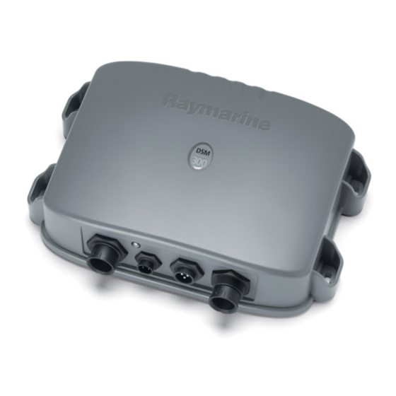
- Page 1 DSM300 Digital Sounder Module nstallation Manual Document number: 87048-1 Date: November 2004...
-
Page 2: Trademarks And Registered Trademarks
Trademarks and registered trademarks HSB, Raymarine and SeaTalk are registered trademarks of Raymarine Limited. All other product names are trademarks or registered trademarks of their respective owners. Contents of this handbook ©Raymarine 2004... -
Page 3: Table Of Contents
EMC Conformance ... 6 Conventions ... 6 Technical Accuracy ... 6 Warranty ... 6 Chapter 1: DSM300 Installation ...7 1.1 Introduction ... 7 Planning the Installation ... 7 EMC Installation Guidelines ... 7 1.2 Unpacking and Inspecting the Components ... 9 1.3 Selecting Sounder Module Mounting Location ... - Page 4 EMC Servicing and Safety Guidelines ...58 3.2 Resetting the System ...59 3.3 Problem Solving ...61 Common Problems and Their Solutions ...61 Status LED ...62 3.4 How to Contact Raymarine ...64 On the Internet ...64 In the US ...64 In Europe ...66 Worldwide Support ...66 Appendix A: Specifications...67...
-
Page 5: Preface
If the transducer cable is accidentally removed while the DSM300 is powered on, remove power from the sounder module, replace the transducer cable, and then return power to the module. As a safety feature, the DSM300 only recognizes that the transducer is connected at power-up. -
Page 6: Emc Conformance
Technical Accuracy To the best of our knowledge, the technical and graphical information contained in this handbook was correct as it went to press. However, the Raymarine policy of continuous improvement and updating may change product specifications without prior notice. As a result, unavoidable differences between the product and handbook may occur from time to time, for which liability cannot be accepted by Raymarine. -
Page 7: Chapter 1: Dsm300 Installation
Chapter 1: DSM300 Installation 1.1 Introduction This chapter provides details for mounting the DSM300 and connecting to the display. For the system to display depth, water temperature and speed, you must install the transducer type(s) capable of transmitting the appropriate data. Transducer information is provided in Chapter 2. -
Page 8: Suppression Ferrites
Figure 1-1: Typical Suppression Ferrites Connections to Other Equipment If your Raymarine equipment is to be connected to other equipment using a cable not supplied by Raymarine, a suppression ferrite must always be attached to the cable that is closest to the Raymarine unit. -
Page 9: Unpacking And Inspecting The Components
Manual Installation Manual, part no. 87048 A 3m-long cable is included for connecting your DSM300 to a C Series display. Longer cables and connection cables for other types of systems must be purchased separately. Select from the following: Table 1-1: Cable Options... -
Page 10: Selecting Sounder Module Mounting Location
1.3 Selecting Sounder Module Mounting Location The DSM300 is waterproof to IPX-7 is and is designed to be mounted either above or below deck. Mount the DSM300 where it is: • protected from physical damage and excessive vibration • protected from prolonged exposure to rain, salt spray and direct sunlight •... -
Page 11: Mounting The Sounder Module
Chapter 1: DSM300 Installation 1.4 Mounting the Sounder Module The DSM300 can be mounted either above or below deck using the supplied hardware. To allow for ease of cable connection, mount the sounder module so that the cables hang below the unit. - Page 12 3/8" diame- ter. 4. Drive the supplied #8 screws into the pilot holes. Screw them in about half way. 5. Mount the module to the surface, slipping the screw heads through the four key holes. DSM300 Installation Manual D7479-1 D7538-1...
- Page 13 Chapter 1: DSM300 Installation 6. Press the module downward so the screws align with the narrow end of the keyholes. i m u m i n D7480-1 7. Tighten the screws. Do not overtighten. Figure 1-3: Properly Mounted DSM300...
-
Page 14: Cable Runs
The power cable may be extended by up to 60 ft (20 m) using a wire gauge of AWG 12 or greater. The DSM300 is intended for use on boat’s DC power systems rated from 10.7 V to 32 V. -
Page 15: System Connections
The following sections detail the connectors used when installing the DSM300. DC Power Connection The DSM300 is intended for use on boat’s DC power systems rated from 10.7 V to 32 V. The power connection to the unit should be made at either the output of the battery isolator switch or at a DC power distribution panel. - Page 16 You should locate the DSM300 so that the power cord can be easily removed, if Note: necessary. If the sounder is placed in a difficult-to-reach location, Raymarine strongly suggests installing an on/off switch on the DSM300 power cord at a point where it is easily accessible. DSM300 Installation Manual...
-
Page 17: Transducer Connection
It is important that an effective RF ground is connected to the system. A single ground point should be used for all equipment. You can ground the DSM300 by connecting the drain wire (shield) of the Power Input cable to the boat’s RF ground. - Page 18 This system is not intended for use on “positive” ground vessels. DSM300 used Transducer Figure 1-8: Using the DSM300 with an E Series Display DSM300 Transducer Figure 1-9: Using the DSM300 with a C Series Display Power Supply Crossover Coupler...
- Page 19 Chapter 1: DSM300 Installation Power Supply DSM300 hsb PLUS Series Display Unit used Transducer Figure 1-10: Using the DSM300 with an hsb PLUS Series Display...
-
Page 20: Configuration
The E Series system operates on the SeaTalk RJ-45 modular connector. See Table 1-1 for a list of available E Series cables. When the DSM300 is used with a single display, connection is made via a SeaTalk Crossover Coupler. E Series Display... - Page 21 The C Series system uses cables with a round 4-pin twist-lock network connector. A 3m-long C Series cable is included with your DSM300. If a longer cable is required, an optional 10m C Series cable (part number E65011) is available from Raymarine.
- Page 22 If a PLUS Series display is the last device on the network, an inline terminator is installed on the cable where it connects to the display. The network connection in the DSM300, however, is internally terminated; it does not require an inline terminator.
-
Page 23: Chapter 2: Transducer Installation
Transducers enable fishfinder systems to display depth, water temperature and/or speed information, depending on the type of transducer(s) installed. This chapter describes the transducers that are available for use with the DSM300. This chapter also provides general information for installing the three main types of transducers: transom mount, thru-hull and in-hull. - Page 24 The DSM300 can be used with any of the following transducers: Mounting Method Transom Thru-Hull Part No. Sensor (Model) Type Depth 1, 2 E66049 (M260) Depth E66078 (M256) E66019 Speed, (ST69) Temp E66054 Depth, (P66) Speed, Temp E66013 Depth (P319)
-
Page 25: Accessories
Chapter 2: Transducer Installation Mounting Method In-Hull Accessories The following optional equipment is also available from Raymarine for your transducer: Table 2-1: Accessories Item Transducer Extension Cable, 10 ft (3 m) Transducer Extension Cable, 18 ft (5 m) Transducer Y-Cable... -
Page 26: Transducer Cable
• If the 30 ft (10 m) cable is not long enough, extension cables are available from your Raymarine dealer. See Table 2-1 on page 25. Total cable length from the transducer to the DSM must not exceed 60 ft (20 m). When you attach the extension cable, be sure that the connections are watertight. - Page 27 Chapter 2: Transducer Installation Before attaching the transducer cable, you will need to attach the connector nut and split ring. These items, plus a wedge tool, are included in the transducer packaging. Figure 2-1: Assembling the Transducer Connector ➤ To attach the transducer cable connector: 1.
- Page 28 • Combined speed/temperature transducers have a 3 pin female con- nector that requires the use of an additional Y-shaped cable (Raymarine part number E66022) to attach to the 7 pin connector on the DSM300. This Y-cable is included with your speed/temperature transducer.
-
Page 29: Selecting The Equipment Location
Chapter 2: Transducer Installation Figure 2-2: Installing the Cable on a Transom Mount Transducer 2.3 Selecting the Equipment Location Transducer Mounting Location It is very important that you mount the transducer correctly. The transducer provides the most reliable readings if it looks into water that is smooth and undisturbed. -
Page 30: Transom Mount Transducer
• If the propeller can be turned to steer the boat, allow at least 2" (50 mm) beyond the swing radius of the propeller. This will prevent the propeller from damaging the transducer when it is turned. DSM300 Installation Manual... - Page 31 Chapter 2: Transducer Installation Figure 2-3: Transom Mount Transducer Location • Do not mount the transducer behind any hull fittings, intakes or other parts extending from the hull that may cause turbulence or air bubbles. • The bracket has a quick-release mechanism, shown Figure 2-4 . This allows the transducer to flip up if it hits any debris or the bottom.
- Page 32 • Planing hull powerboat – Mount well aft, on or near the centerline, and well inboard of the first set of lifting strakes to ensure that it is in contact with the water at high speeds. Mount on the side of the hull where the propeller is moving downward. DSM300 Installation Manual...
- Page 33 Chapter 2: Transducer Installation Outboard and I/O – Mount just forward of the engine(s). Inboard – mount well forward of the propeller(s) and shaft(s). Step-hull – Mount just ahead of the first step. Boats capable of speeds above 25 kn (29 m.p.h.) – Review transducer location and operating results of similar boats before proceeding.
- Page 34 DSM300 Installation Manual Figure 2-6: Best Location for Thru Hull Transducer...
-
Page 35: Installing The Transom Mount Transducer
Chapter 2: Transducer Installation 2.4 Installing the Transom Mount Transducer Preparation Transducer Mounting Bracket When installed, the lower surface of the transducer should tilt down toward the rear at a slight angle (2° to 5°). The mounting bracket includes a wedge; depending on the angle of the transom on your boat, you may need to install this wedge to get the correct transducer angle. -
Page 36: Installation
5. Once the bracket is in the correct position tighten the screws. 2.5 Installing the Thru-hull Transducer Tools and Material Needed Water-based antifouling paint (mandatory for boats kept in salt water) Safety goggles Dust mask Electric drill Drill bit: 1/8" (3 mm) DSM300 Installation Manual... -
Page 37: Preparation
Chapter 2: Transducer Installation Hole saw: Fiberglass or wood Aluminium or steel hull Sandpaper File (for installation in a metal hull) Mild household detergent or weak solvent (alcohol) Marine sealant Slip-joint pliers Silicone grease or petroleum jelly Tie-wraps Cored fiberglass hull installation: Hole saw for hull interior 2-3/8"... - Page 38 (see Figure 2-9 ). After cutting the fairing, use the remaining section with the cutting guide as the backing block (see Figure 2-10 ). Used with Transducer No. (model) E66056 (B744V) E66057 (B744VL) E66024 (B256) E66033 (B260) DSM300 Installation Manual Max. Hull Thickness with Fairing " (26mm) " 3-3/4 (87mm) "...
- Page 39 Chapter 2: Transducer Installation Figure 2-10: Transducer Fairing Cutting the Fairing 1. Measure the deadrise angle of the hull at the selected location using a digital level, or bubble level and protractor (see Figure 2-9 ). 2. Tilt the band saw table to the measured angle and secure the cutting fence (see Figure 2-11 ).
-
Page 40: Anti-Fouling Paint
Exposed area of the housing, including the acoustic window Bore of the housing up to 1-1/4" (30 mm) Outside wall below lower O-ring Exposed end of the paddle wheel insert Paddle wheel cavity Paddle wheel Blanking plug below the lower O-ring and the exposed end DSM300 Installation Manual... -
Page 41: Installation
Chapter 2: Transducer Installation Figure 2-12: Applying Antifouling Paint Installation To install the thru-hull transducer in a cored fiberglass hull, follow the instructions Note: in Installation in a Cored Fiberglass Hull on page 48. Drilling Holes CAUTION: Always wear safety goggles and a dust mask when drilling. 1. - Page 42 Seat the transducer firmly in the recess in the fairing. The transducer must be flush with the fairing. If it is recessed more than 1/64" Note: (0.5mm) inside the fairing, you may carefully file or sand the fairing flush with the transducer. DSM300 Installation Manual...
- Page 43 Chapter 2: Transducer Installation CAUTION: Always wear safety goggles and a dust mask. 3. Attach the drill bit to your drill appropriate for your fairing: Fairing E66023 E66025 E66034 4. Slide the transducer’s stem with the fairing in place into the mounting hole. Be sure the triangular recess in the fairing is pointing forward toward the bow.
-
Page 44: Attaching The Transducer
6. Push the bolt through the fairing, if used, and into the hull. 7. From inside the hull, slide the washer and nut onto the bolt. Screw the nut in place and tighten it with slip-joint pliers. Wood hull - Allow for the wood to swell. DSM300 Installation Manual... - Page 45 Chapter 2: Transducer Installation Figure 2-15: Fore View of Transducer Installation 8. If a fairing is used, apply marine sealant to the flat side of the triangular plug. Push the plug into the triangular recess in the fairing. The triangular plug fits one way only.
- Page 46 To reduce electrical interference, separate the transducer cable from other electrical wiring and the engine. 19. Coil any excess cable and secure it in place using tie-wraps to prevent damage. page 26 DSM300 Installation Manual Transducer Cable...
- Page 47 Chapter 2: Transducer Installation Figure 2-16: Servicing the Paddle Wheel Insert and Valve Assembly...
-
Page 48: Installation In A Cored Fiberglass Hull
5. Coat a hollow or solid cylinder of the correct diameter with wax and tape it in place. Fill the gap between the cylinder and hull with casting epoxy. After the epoxy has set, remove the cylinder (see Figure 2-17 ). DSM300 Installation Manual... -
Page 49: Check For Leaks
Chapter 2: Transducer Installation Figure 2-17: Preparing a Cored Fiberglass Hull 6. Sand and clean the area around the hole, inside and outside, to ensure that the sealant will adhere properly to the hull. If there is any petroleum residue inside the hull, remove it with either mild household detergent or a weak sol- vent (alcohol) before sanding. -
Page 50: Installing The In-Hull Transducer
1. Take the boat to the maximum depth for which your instrument is rated, or the maximum depth in which you will operate the sounder. 2. Connect the transducer to the DSM. Refer to page 26 DSM300 Installation Manual Transducer Cable Connections... - Page 51 Chapter 2: Transducer Installation 3. Tape the transducer to a pole with the cable side up. Hold it over the side of the boat with the active face submerged in the water (see Figure 2-18 ). Keep the active face of the transducer parallel to the surface of the water. 4.
-
Page 52: Installation
3. Remove any dust, grease or oil with a weak solvent, such as alcohol, to ensure a good bond. Clean and dry both the selected area and the underside of the base. Installation in a Cored Fiberglass Hull DSM300 Installation Manual page 55... - Page 53 Chapter 2: Transducer Installation 4. Using a carpenter’s square, draw a line on the hull perpendicular to the keel through the center of the mounting location. This will be used as a guideline to orient the base. Figure 2-20: Deadrise Angle 5.
- Page 54 To secure the housing to the lock- ing ring, insert two screws (see Figure 2-22 ). Do not overtighten the screws. Figure 2-22: Joining the Transducer Housing to the Locking Ring DSM300 Installation Manual...
-
Page 55: Installation In A Cored Fiberglass Hull
Chapter 2: Transducer Installation 8. Lubricate the O-ring with silicone grease or petroleum jelly. Slide the O-ring onto the transducer assembly (see Figure 2-23 ). Figure 2-23: Installing the O-ring 9. When the adhesive on the base has cured, pour 2.4 fl. oz. (71 mil) of mineral oil into the base. - Page 56 Pour this around the housing until the cavity is full. Allow the casting epoxy to set for at least 1 hour. Figure 2-24: Installation in a Cored Fiberglass Hull 5. Proceed with step 7 of “Installation” on page 54. DSM300 Installation Manual...
-
Page 57: Chapter 3: Maintenance And Problem Solving
• Check that the cable connectors are firmly attached. Cleaning Instructions Cleaning the Module The DSM300 is a sealed unit and does not require regular cleaning. However, if you find it necessary to clean the unit, please follow these basic procedures: • Ensure power is off. -
Page 58: Emc Servicing And Safety Guidelines
EMC Servicing and Safety Guidelines • Raymarine equipment should be serviced only by authorized Raymarine ser- vice technicians. They will ensure that service procedures and replacement parts used will not affect performance. There are no user serviceable parts in any Raymarine product. -
Page 59: Resetting The System
Chapter 3: Maintenance and Problem Solving 3.2 Resetting the System The Reset function returns the DSM300 to its factory default values. How you perform the reset depends on the type of display the sounder module is connected CAUTION: Factory Reset The factory reset clears the sonar depth offset and speed and temperature calibrations. - Page 60 DSM300 Installation Manual iii. An audible alarm is sounded. iv. The normal sonar image resumes scrolling across the display. The reset is complete. ➤ To cancel the reset: Before pressing YES as described in item 4 above, press any of the following keys: DISPLAY, MULTI, VRM/EBL, MARKS, RANGE, GAIN, or ALARMS.
-
Page 61: Problem Solving
Chapter 3: Maintenance and Problem Solving 3.3 Problem Solving All Raymarine products are, prior to packing and shipping, subjected to comprehensive test and quality assurance programs. However, if this unit should develop a fault, please refer to the following table to identify the most likely cause and the corrective action required to restore normal operation. -
Page 62: Status Led
The LED on the connector panel provides valuable information on the status of your DSM300. The LED blinks green while the module is operating normally. If the unit detects a problem, the LED blinks amber to indicate a warning or red for an error. - Page 63 A solid red LED (not blinking) indicates a fatal error condition. If the event of a fatal error, the system will power cycle to attempt to self-correct the condition. If the condition persists, please contact Raymarine Customer Service. No of...
-
Page 64: How To Contact Raymarine
If the answer you are seeking is not available, click the Ask Raymarine tab to submit your own question to our technical support staff, who will reply to you by e-mail. -
Page 65: Product Repair And Service
Questions can be sent directly to our Technical Support Department via the Internet. Point your browser to www.raymarine.com and click on the Customer Support link. From there, select Find Answers and click the Ask Raymarine tab. Product Repair and Service In the unlikely event your Raymarine unit should develop a problem, please contact your authorized Raymarine dealer for assistance. -
Page 66: In Europe
Installation chapter of this manual and have the Raymarine part number ready when speaking with your dealer. If you are uncertain about what item to choose for your Raymarine unit, please contact our Customer Services Department prior to placing your order. -
Page 67: Appendix A: Specifications
Appendix A: Specifications Appendix A: Specifications General Approvals: CE - conform to Size: Weight: Mounting Power: Voltage Current Fuse Environmental: Operating Range: Storage Range: Humidity: Connectors Sounder Features with standard transducer Output Adjustable to 600 watts RMS Power: Frequency Dual 50 kHz and 200 kHz Pulse 100 µsec to 4 msec Length:... - Page 68 DSM300 Installation Manual...
-
Page 69: Index
Installation Guidelines 7 Servicing & Safety Guidelines 58 Error codes 62 Factory Reset 59 Fairing 25 Ground Connection 17 Help from Raymarine 64 High Voltage 5 In-hull Transducer Installation 50 Cored Fiberglass hull 55 Location 32 Installation Cable Runs 7... - Page 70 Maintenance 57 Mounting the DSM300 11 Network Configuration 20 Network Switch 20 Options DSM300 9 Transducer 25 Power Connection 15 Reset 59 Routine Checks 57 Safety 5 EMC Guidelines 9 High Voltage 5 SeaTalk hs Connections 15 SeaTalk hs Crossover Coupler 20...
Need help?
Do you have a question about the DSM300 and is the answer not in the manual?
Questions and answers