Table of Contents
Advertisement
Quick Links
Advertisement
Table of Contents

Related Manuals for Mira BB-86 Mini

Summary of Contents for Mira BB-86 Mini
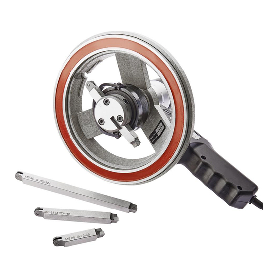
- Page 1 Instruction manual English (EN) Unit for precise sleeve counterbore operations...
-
Page 2: Table Of Contents
Non-liability ............................... 8 Warranty ..............................8 Declaration of conformity BB-86 Standard ..................... 9 Declaration of conformity BB-86 Mini ....................10 Declaration of conformity BB-86 Giant ....................11 Description of parts ......................... 13 Performance system of the BB-86 unit ..................14 Working method .......................... -
Page 3: Safety Regulations
There is a risk of injury by the cutting bit which is attached to the rotating spindle! Unplug the device before working on electronic components! In all cases, repairs to the tool are only allowed to be performed by the local MIRA-dealer or the manufacturer => (MINELLICorporation)! Only use genuine MIRA spare parts, which are listed in the respective instruction manual! DO NOT touch the electric circuits of the device. -
Page 4: Basic Safety Guidelines
Operating risks The devices, BB-86, BB-86 Giant and BB-86 Mini, have been developed based on the latest state- of-the-art technology, and were manufactured in accordance with the governing safety regulations. However, it is possible by using these devices that some risks could appear for the user or third persons if the devices are not operated according to the MIRA instruction manual, or if they are misused. - Page 5 Warranty and liability Warranty issues are described in MIRA‘s terms of sales and return policy conditions, and are an integral part of any sales contract between MIRA and the customer. Warranty and liability claims are void if the injuries or damages resulted from any of the following causes: ➢...
- Page 6 • The rotary cutting bit has very sharp and jagged edges and can cause severe lacerations or others injures. Exercise caution when processing the counterbore sleeves! • The BB-86, BB-86 Giant and BB-86 Mini have rotating machine parts which present a risk for (long) hair, hands and fingers. Wear suitable personal safety protection equipment (e.g. hairnet, gloves etc.).
- Page 7 Noise emission of the device • The sound pressure level emitted by the BB-86, BB-86 Giant and BB-86 Mini, is rated at 30dB(A) • When the BB-86 is used in combination with the Vario Drive System, there is a sound pressure level up to 70dB(A) emitted from the Vario Drive.
-
Page 8: Copyright
Copyright © The exclusive copyright of this instruction manual belongs to the MINELLI Corporation (MIRA). This instruction manual is provided to the operator and his personnel. Minelli Corporation MIRA Division Mattenstrasse 3 8330 Pfäffikon ZH Switzerland CH For the provided technical documentation see the authorised person in chapter „Declaration of conformity”... -
Page 9: Non-Liability
Non-liability The BB-86 turning device for sleeve counterbore procedures may only be operated according to the Operating Instructions. The manufacturer refuses to accept any liability for accidents and damages caused by incorrect operation. He also refuses any liability for unintended use of the device. Warranty In case of manufacturing or material defects, Minelli Corporation will replace the defective part or parts at no charge, within 24 months of the date of purchase. -
Page 10: Declaration Of Conformity Bb-86 Standard
Declaration of conformity BB-86 Standard 19 July 2023/v1.7 BB-86 | Serial-No. 865 / 0609 © (All rights reserved) -
Page 11: Declaration Of Conformity Bb-86 Mini
Declaration of conformity BB-86 Mini 19 July 2023/v1.7 BB-86 | Serial-No. 865 / 0609 © (All rights reserved) -
Page 12: Declaration Of Conformity Bb-86 Giant
Declaration of conformity BB-86 Giant 19 July 2023/v1.7 BB-86 | Serial-No. 865 / 0609 © (All rights reserved) - Page 13 Processing of counterbore seats The MIRA BB-device is simple to operate and the procedure is very fast and precise. After insertion of the correct cutting tool, the device is placed onto the clean cylinderblock surface. The centering is done by means of a roller device which is on the backside of the cutting tool, and guides the cross feed.
-
Page 14: Description Of Parts
1 Description of parts Advancing Crank handle mechanism Vernier Worm screw Locking screw Tumbler switch Magnetic base Handle (220V/110V) Gear bushing Turning tool with Power cord Specification hard carbide tip label Cover Centering roll Main spindle plate To avoid accidents from an electrical shock, unplug the power cord from the It is recommended that the magnetic electrical outlet first! After that, repairs... -
Page 15: Performance System Of The Bb-86 Unit
1. Electro-magnetic base BB-86: • Attaches directly onto the engine block (See page 22) • or onto the intercostal plate (See page 28) • or onto the MIRA Repair ring (See page 36) Figure 4 2. Tumbler switch Pos. 1... - Page 16 3. Vertical feed with advancing mechanism Adjusts the depth of the turning tool. Figure 5 Vernier is adjustable to 0 (See step 14 on page 25) 1 Revolution = 1mm 1 Graduation mark = 0.01mm (1/100mm) Figure 5 4. Bow For inserting, removing and quick setting of the turning tool.
-
Page 17: Working Method
3 Working method This picture shows the important working Depending on the specifications of the engine surfaces. These are the sealing surface of the manufacturer, the inserted sleeve can be block and the sealing and bearing surface of protruding or recessed. the sleeve collar. -
Page 18: Example B
Protrusion Counterbore-Ø Sealing shim Engine block 3.2 Example B If an engine is only partially dismounted or only one counterbore needs work, the situation changes. In such a case the block is not re-surfaced. Instead, the leaky sleeve has to be replaced by an oversized sleeve, or a sealing sheet needs to be applied to the standard sleeve. -
Page 19: Turning Tools And Their Application
4 Turning tools and their application Standard counterbore seat turning tool Turning tool for engines with intercoastal plate or with interrupted counterbore wall Center-Ø Working-Ø Remarks Order- Center-Ø Working-Ø Remarks Order-No.: d (mm) D (mm) No.: d (mm) D (mm) MB-85 73-86 67-86... - Page 20 Special tools for aluminium cylinderheads Center-Ø Working-Ø Remarks Center-Ø Working-Ø Remarks Order-No.: Order-No.: d (mm) D (mm) d (mm) D (mm) Deutz, Deutz MB-91/1 120-150 154-150 MB-92 90-124 84-124 Daf, MB-108 106-122 100-122 Güldner MB-93 73-88 67-88 Porsche Special tools for counterbore seat corresponding to construction specifications Center-Ø...
- Page 21 Center-Ø Working-Ø Remarks Center-Ø Working-Ø Remarks Order-No.: Order-No.: d (mm) D (mm) d (mm) D (mm) Cummins MB88CUM1.0 123-160 111-160 MB88DAF0.3 123-160 111-160 Center-Ø Working-Ø Remarks Center-Ø Working-Ø Remarks Order-No.: Order-No.: d (mm) D (mm) d (mm) D (mm) DAF, DAF, MB88DAF0.8 123-160...
-
Page 22: Working Process
5 Working process WARNING! For perfect results, the following points are essential: The BB turning tool has sharp and pointed edges and must be • The unit must be well grounded handled carefully. • The unit must be clean • The set up area must be absolutely clean In addition, the magnetic base poses a risk of pinching hands or... - Page 23 4. Using both hands, place the unit on top of the cleaned set up area (the handle is positioned to left in this example). Connect the power cord to an electrical outlet. Figure 12 Figure 12 5. Place the unit slightly off center to the counterbore. The greater distance to the center of the unit should be on the opposite side of the handle.
- Page 24 7. Push the bow and place the centering roller against the counterbore wall at the point where the centering distance is the largest. Release the bow and move the tumbler switch to the center position. Figure 15 Figure 15 8. To center the unit, hold the gear bushing with 2 fingers and turn the crank handle clockwise.
- Page 25 9. After the device has been perfectly centered, set the tumbler switch to position ”1”. Check: After the magnet has been engaged, the crank handle must turn freely and the centering roller should make light contact with the entire circumference of the counterbore wall.
- Page 26 Push the bow and return the turning tool to the free space with the hard metal tip positioned just above the counterbore. Figure 20 Figure 20 Loosen the locking screw and set the correct depth by using the advancing mechanism. Reblock the locking screw.
- Page 27 Figure 24 The level height above the engine surface is: BB-86 Standard 35.00mm (1.378 In) BB-86 Mini 35.00mm (1.378 In) BB-86 Giant 32.00mm (1.259 In) Figure 24 Press the bow downwards and push the turning tool until the centering roller touches the counterbore wall.
- Page 28 Move the tumbler switch to position „2“, then back to the middle position. Then remove the unit with both hands. Figure 26 Figure 26 Clean the metal particles from the device and place it onto the clean surface above the next counterbore.
-
Page 29: Special Applications
2. Preparation of a counterbore seat for a dry sleeve Set the correct diameter and fix the pressure bolt for the turning tool, then proceed by using the advancing mechanism. MIRA Set-up area 3. Process with screwed-on intercostal Fastening The bridge-over steel plate is not available as a onto the standard item. -
Page 30: Service And Maintenance
7 Service and maintenance α 7.1 Grinding of the turning tools Angle specifications α β γ δ ε φ Tool type MB β 0° 2° 2° 0° 5° 5° 85, 86, 87, 88, 98, 90 5° 5° 1° 2° 0° 5°... -
Page 31: Lubrication Of The Main Spindle And The Advancing Mechanism
7.3 Lubrication of the main spindle and the advancing mechanism Annual service: 1. Remove vernier from advancing mechanism (loosen worm screw (E)), but leave it on the spindle guide (G). 2. Loosen special nut (A) and remove adapter or crank handle (J). -
Page 32: Spare Parts Bb-86 Main Spindle
To ensure precise functioning of the main spindle and to avoid damage, corresponding replacement work should only be carried out by an authorised MIRA specialist dealer or by the manufacturer. 19 July 2023/v1.7 BB-86 | Serial-No. 865 / 0609 ©... -
Page 33: Spare Parts Bb-86 Units
9 Spare parts BB-86 units (BB-86 Standard, BB-86 Mini and BB-86 Giant with mains voltage 230 / 110VAC and 50 / 60Hz) When ordering spare parts, the serial- and the manufacturing number of the units must always be indicated. Spare parts valid with Serial-No.: 865 and 0609 from manufacturing-No.: 6000<... - Page 34 Description Pos. Part-No.: Magnetic base 230V MD-20 (BB-86 Mini) 18042.2.5079 Magnetic base 110V MD-10 (BB-86 Mini) 18042.2.6741 Type plate MD-20 (BB-86 Mini) 18042.4.5084A Type plate MD-10 (BB-86 Mini) 18042.4.5084B Magnetic base 230V MG-20(BB-86 Giant) 18042.2.1422A Magnetic base 110V MG-10 (BB-86 Giant) *95 18042.2.1422B...
-
Page 35: Assembly Drawing Bb-86 Units
10 Assembly drawing BB-86 units (BB-86 Standard, BB-86 Mini and BB-86 Giant with mains voltage 230 / 110VAC and 50 / 60Hz) BB-86 Standard BB-86 Giant BB-86 Mini 19 July 2023/v1.7 BB-86 | Serial-No. 865 / 0609 © (All rights reserved) -
Page 36: Schematic Diagram
11 Schematic diagram 19 July 2023/v1.7 BB-86 | Serial-No. 865 / 0609 © (All rights reserved) -
Page 37: Special Accessories
12 Special accessories MIRA tooling equipment for the BB-86 series is available on the MIRA Webshop: (See below a few equipment possibilities) 1. Sealing groove cutting sets for cylinderheads For deep counterbore seat applications to a maximum depth of 220mm. Compatible with all BB- 86 devices (Standard, Mini, Giant). - Page 38 Notes 19 July 2023/v1.7 BB-86 | Serial-No. 865 / 0609 © (All rights reserved)
- Page 39 Notes 19 July 2023/v1.7 BB-86 | Serial-No. 865 / 0609 © (All rights reserved)
- Page 40 Manufacturer and worldwide distributor: Your local distributor: MINELLI CORPORATION Mattenstrasse 3 8330 Pfäffikon ZH Switzerland www.miratool.ch 19 July 2023/v1.7 BB-86 | Serial-No. 865 / 0609 © (All rights reserved)
Need help?
Do you have a question about the BB-86 Mini and is the answer not in the manual?
Questions and answers