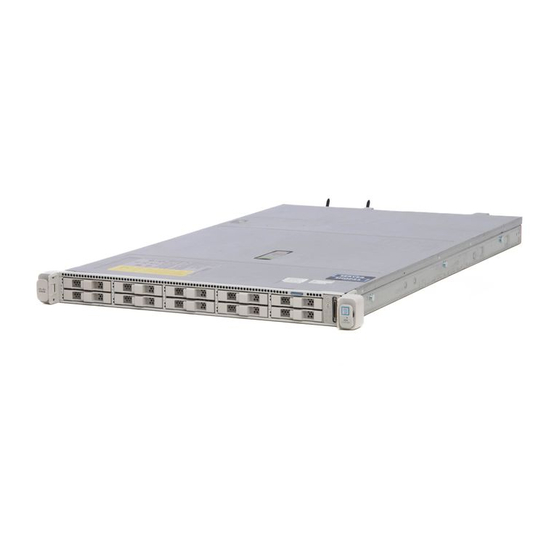
Cisco Threat Grid M5 Maintenance Manual
Hide thumbs
Also See for Threat Grid M5:
- Basic user's manual (12 pages) ,
- Hardware installation manual (42 pages)
Advertisement
Maintenance and Upgrades
•
•
•
Power Button Shut Down
The Threat Grid M5 runs in two modes:
• Main power mode—Power is supplied to all Threat Grid M5 components and all operating systems can
• Standby power mode—Power is supplied only to the service processor and certain components. You can
Caution
After you shut down the Threat Grid M5 to standby power, electric current is still present in the chassis. To
completely remove power as directed in some maintenance procedures, you must disconnect all power cords
from all power supplies on the Threat Grid M5.
You can shut down the Threat Grid M5 using the front panel Power button or use OpAdmin to initiate a reboot
or shutdown.
Step 1
Check the Power LED:
• Amber—The Threat Grid M5 is already in standby mode and you can safely remove power.
• Green—The Threat Grid M5 is in main power mode and you must shut it down before you can safely remove power.
Step 2
Perform a graceful shutdown or a hard shutdown:
Caution
To avoid data loss or damage to your operating system, perform a graceful shutdown of the operating system.
• Graceful shutdown—Press and release the Power button. The operating system performs a graceful shutdown and
the Threat Grid M5 goes into standby mode. The power LED is amber.
• Emergency shutdown—Press and hold the Power button for four seconds to force the main power off and immediately
enter standby mode.
Power Button Shut Down, on page 1
Remove And Replace A Drive, on page 2
Remove And Replace A Power Supply, on page 4
run.
safely remove power cords from the Threat Grid M5 in this mode.
Maintenance and Upgrades
1
Advertisement
Table of Contents

Summary of Contents for Cisco Threat Grid M5
- Page 1 • Amber—The Threat Grid M5 is already in standby mode and you can safely remove power. • Green—The Threat Grid M5 is in main power mode and you must shut it down before you can safely remove power. Step 2...
- Page 2 Remove and Replace a Drive Note The drives are hot-swappable. You do not have to shut down the Threat Grid M5 to remove or replace drives. Note You cannot add more drives to the chassis. You can only replace the drives in the slots that shipped with your Threat Grid M5.
- Page 3 Maintenance and Upgrades Remove and Replace a Drive Warning Statement 1073 No User-Serviceable Parts There are no serviceable parts inside. To avoid risk of electric shock, do not open. Warning Statement 1074 Comply with Local and National Electrical Codes To reduce risk of electric shock or fire, installation of the equipment must comply with local and national electrical codes.
- Page 4 2 is put into a standby state. Caution When you replace power supplies, do not mix power supply types in the Threat Grid M5. Both power supplies must be the same wattage and Cisco PID. Maintenance and Upgrades...
- Page 5 Maintenance and Upgrades Remove and Replace a Power Supply Trouble Power supply health monitoring notifies you if the power supply loses power or malfunctions so that redundancy is lost. Check the power supply cables to make sure they are functioning. If they are and errors are still occurring, replace the power supply.
- Page 6 Push the power supply into the bay until the release lever locks. c) Connect the power cord to the new power supply. d) If you shut down the Threat Grid M5, press the Power button to return it to main power mode. Maintenance and Upgrades...


Need help?
Do you have a question about the Threat Grid M5 and is the answer not in the manual?
Questions and answers