Cisco Threat Grid M5 Hardware Installation Manual
Hide thumbs
Also See for Threat Grid M5:
- Basic user's manual (12 pages) ,
- Maintenance manual (6 pages)
Table of Contents
Advertisement
Quick Links
Advertisement
Table of Contents

Subscribe to Our Youtube Channel
Related Manuals for Cisco Threat Grid M5


Summary of Contents for Cisco Threat Grid M5
- Page 1 Cisco Threat Grid M5 Hardware Installation Guide First Published: 2019-12-20 Americas Headquarters Cisco Systems, Inc. 170 West Tasman Drive San Jose, CA 95134-1706 http://www.cisco.com Tel: 408 526-4000 800 553-NETS (6387) Fax: 408 527-0883...
- Page 2 Cisco has more than 200 offices worldwide. Addresses and phone numbers are listed on the Cisco website at www.cisco.com/go/offices. Cisco and the Cisco logo are trademarks or registered trademarks of Cisco and/or its affiliates in the U.S. and other countries. To view a list of Cisco trademarks, go to this URL: www.cisco.com...
-
Page 3: Table Of Contents
Power Supply Considerations Rack Configuration Considerations C H A P T E R 3 Rack-Mount the Chassis Unpack and Inspect the Chassis Rack-Mount the Chassis Connect Cables, Turn on Power, and Verify Connectivity Cisco Threat Grid M5 Hardware Installation Guide... - Page 4 Contents C H A P T E R 4 Maintenance and Upgrades Power Button Shut Down Remove and Replace a Drive Remove and Replace a Power Supply Cisco Threat Grid M5 Hardware Installation Guide...
-
Page 5: Overview
IDs (PIDs) associated with the Threat Grid M5 appliance. You can remove and replace drives and power supplies. For all other internal component failures, you must send your chassis for return material authorization (RMA). - Page 6 M5. Although other SFPs may work, we only support these two on the Threat Grid M5. Serial console port RJ45 serial port running RS-232 (RS-232D TIA-561) System power Two 770-W AC power supplies Hot-swappable and redundant as 1+1 Power consumption 2626 BTU/hr Cisco Threat Grid M5 Hardware Installation Guide...
-
Page 7: Package Contents
RAID 1, hot-swappable Package Contents The following figure shows the package contents for the Threat Grid M5. Note that the contents are subject to change and your exact contents might contain additional or fewer items. Figure 1: Threat Grid M5 Package Contents... -
Page 8: Serial Number Location
Two 10-Gb transceivers with cables Serial Number Location The serial number (SN) for the Threat Grid M5 is printed on the pullout asset card located on the front panel as shown in the following figure. Figure 2: Serial Number on Pullout Asset Card The serial number is also on the label on the cover of the chassis as shown in the following figure. -
Page 9: Front Panel
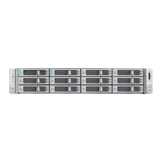
Cover latch Not supported Front Panel The following figure shows the front panel features and disk-drive configuration for the Threat Grid M5. See Front Panel LEDs , on page 6 for a description of the LEDs. Figure 4: Threat Grid M5 Front Panel... -
Page 10: Front Panel Leds
• Amber—Drive fault detected. • Green—The drive is ready. • Amber, flashing—The drive is rebuilding. • Green, flashing—The drive is • Amber, flashing with 1-second interval—Drive locate reading or writing data. function activated in the software. Cisco Threat Grid M5 Hardware Installation Guide... - Page 11 • Amber, flashing—One or more fans breached the unrecoverable threshold. • Green—One or more Ethernet ports are link-active, but there is no activity. • Green, flashing—One or more Ethernet ports are link-active with activity. Cisco Threat Grid M5 Hardware Installation Guide...
-
Page 12: Rear Panel
• Amber, flashing—One or more temperature sensors breached the unrecoverable threshold. Rear Panel The following figure shows the rear panel of the Threat Grid M5. Figure 6: Rear Panel USB 3.0 Type A (USB 1) USB 3.0 Type A (USB 2) -
Page 13: Rear Panel Leds
• Off—Link speed is 10 Mbps. • Off—No link is present. • Amber—Link speed is 100 Gbps. • Amber—Link is active. • Green—Link speed is 1 Gbps. • Green, flashing—Traffic is present on the active link. Cisco Threat Grid M5 Hardware Installation Guide... -
Page 14: Power Supply
• Amber—Critical error detected; 12-V main power off (for example, overcurrent, overvoltage, or overtemperature failure). Power Supply The following table lists the specifications for each 770-W AC power supply (Cisco part number FMC-PWR-AC-770W) used in the Threat Grid M5. Table 2: Power Supply Specifications Description... -
Page 15: Hardware Specifications
Operation at 73°F (23°C) Product ID Numbers The following table lists the field-replaceable PIDs associated with the Threat Grid M5. The spare components are ones that you can order and replace yourself. If any internal components fail, you must RMA the entire chassis including the SFPs and SFP cables. -
Page 16: Power Cord Specifications
Each power supply has a separate power cord. Standard power cords or jumper power cords are available for connection to the Threat Grid M5. The jumper power cords for use in racks are available as an optional alternative to the standard power cords If you do not order the optional power cord with the system, you are responsible for selecting the appropriate power cord for the product. - Page 17 Figure 10: Brazil PWR-250V-10A-BZ Plug: NBR 14136 Cord set rating: 10 A, 250 V Connector: IEC 60320/C13 Figure 11: Cabinet Jumper CAB-C13-C14-2M Plug: SS10A Cord set rating: 10A, 250V Connector: HS10S, C-13 to C-14 Cisco Threat Grid M5 Hardware Installation Guide...
- Page 18 Figure 13: Cabinet Jumper CAB-C13-CBN Plug: SS10A Cord set rating: 10 A, 250 V Connector: HS10S, C-13 to C-14 Figure 14: China CAB-250V-10A-CH Plug: GB2099.1/2008 Cord set rating: 10 A, 250 V Connector: IEC 60320/C13 Cisco Threat Grid M5 Hardware Installation Guide...
- Page 19 Figure 16: India CAB-250V-10A-ID Plug: IS 6538-1971 Cord set rating: 16 A, 250 V Connector: IEC 60320-C13 Figure 17: Israel CAB-250V-10A-IS Plug: SI-32 Cord set rating: 10 A, 250 V Connector: IEC 60320-C13 Cisco Threat Grid M5 Hardware Installation Guide...
- Page 20 Figure 19: Japan CAB-JPN-3PIN Plug: JIS 8303 Cord set rating: 12 A, 125 V Connector: IEC 60320/C13 Figure 20: Japan CAB-C13-C14-2M-JP Plug: EN 60320-2-2/E Cord set rating: 10 A, 250 V Connector: EN 60320/C13 to C14 Cisco Threat Grid M5 Hardware Installation Guide...
- Page 21 Figure 22: North America CAB-9K12A-NA Plug: NEMA5-15P Cord set rating: 13 A, 125 V Connector: IEC 60320/C15 Figure 23: North America CAB-N5K6A-NA Plug: NEMA6-15P Cord set rating: 10 A, 125 V Connector: IEC 60320/C13 Cisco Threat Grid M5 Hardware Installation Guide...
- Page 22 Figure 25: Switzerland CAB-9K10A-SW Plug: SEV 1011 (MP232-R) Cord set rating: 10 A, 250 V Connector: IEC 60320/C15 Figure 26: Taiwan CAB-ACTW Plug: EL 302 (CNS10917) Cord set rating: 10 A, 125 V Connector: IEC 60320/C13 Cisco Threat Grid M5 Hardware Installation Guide...
- Page 23 Overview Power Cord Specifications Figure 27: United Kingdom CAB-9K10A-UK Plug: BS1363A/SS145 Cord set rating: 10 A, 250 V Connector: IEC 60320/C15 Cisco Threat Grid M5 Hardware Installation Guide...
- Page 24 Overview Power Cord Specifications Cisco Threat Grid M5 Hardware Installation Guide...
-
Page 25: Installation Preparation
Statement 1005—Circuit Breaker This product relies on the building’s installation for short-circuit (overcurrent) protection. Ensure that the protective device is rated not greater than: USA: 120 V, 15 A (EU: 250 V, 16 A) Cisco Threat Grid M5 Hardware Installation Guide... - Page 26 This equipment must be grounded. To reduce the risk of electric shock, never defeat the ground conductor or operate the equipment in the absence of a suitably installed ground conductor. Contact the appropriate electrical inspection authority or an electrician if you are uncertain that suitable grounding is available. Cisco Threat Grid M5 Hardware Installation Guide...
-
Page 27: Safety Recommendations
Before working on a chassis, be sure the power cord is unplugged. Be sure to read the REGULATORY & COMPLIANCE SAFETY INFORMATION document before installing the Threat Grid chassis. Follow these guidelines when working on equipment powered by electricity: Cisco Threat Grid M5 Hardware Installation Guide... -
Page 28: Prevent Esd Damage
If you are currently experiencing shutdowns or unusually high error rates with your existing equipment, these considerations may help you isolate the cause of failures and prevent future problems. Cisco Threat Grid M5 Hardware Installation Guide... -
Page 29: Power Supply Considerations
• Baffles can help to isolate exhaust air from intake air, which also helps to draw cooling air through the chassis. The best placement of the baffles depends on the airflow patterns in the rack. Experiment with different arrangements to position the baffles effectively. Cisco Threat Grid M5 Hardware Installation Guide... - Page 30 Installation Preparation Rack Configuration Considerations Cisco Threat Grid M5 Hardware Installation Guide...
-
Page 31: Rack-Mount The Chassis
Check for damage and report any discrepancies or damage to your customer service representative. Have the following information ready: • Invoice number of shipper (see the packing slip) • Model and serial number of the damaged unit • Description of damage • Effect of damage on the installation Cisco Threat Grid M5 Hardware Installation Guide... -
Page 32: Rack-Mount The Chassis
• The slide rails for the chassis have an adjustment range of 24 to 36 in. (610 to 914 mm). Note The slide rails supplied by Cisco Systems for the chassis do not require tools for installation if you install them in a rack that has square 0.38-in. (9.6 mm), round 0.28-in. (7.1 mm), or #12-24 UNC threaded holes. - Page 33 Pull the inner slide rails on each assembly out toward the rack front until they hit the internal stops and lock in place. Cisco Threat Grid M5 Hardware Installation Guide...
-
Page 34: Connect Cables, Turn On Power, And Verify Connectivity
AC power supplies have internal grounding and so no additional chassis grounding is required when the supported AC power cords are used. For more information about supported power cords, see Power Cord Specifications, on page Before you begin Take note of the following warnings. Cisco Threat Grid M5 Hardware Installation Guide... - Page 35 Step 1 Connect one Cisco-supported SFP+ transceiver and cable to the far left SFP port. This is eth0 used to manage the Threat Grid M5 through the Opadmin console and should connect to a secure management network.
- Page 36 Step 2 Connect a second Cisco-supported SFP+ transceiver and cable to the SFP port to the right of the eth0 port in Step 1. This is eth1 used to access the console and allows your Threat Grid M5 to monitor traffic.
- Page 37 • Amber—The Threat Grid M5 is already in standby mode and you can safely remove power. • Green—The Threat Grid M5 is in main power mode and you must shut it down before you can safely remove power. Step 2...
- Page 38 Remove and Replace a Drive Note The drives are hot-swappable. You do not have to shut down the Threat Grid M5 to remove or replace drives. Note You cannot add more drives to the chassis. You can only replace the drives in the slots that shipped with your Threat Grid M5.
- Page 39 Grasp and open the ejector lever and then pull the drive tray out of the slot. Figure 32: Remove the Drive Ejector handle Release button Step 2 Remove the four drive-tray screws that secure the drive to the tray and then lift the drive out of the tray. Cisco Threat Grid M5 Hardware Installation Guide...
- Page 40 2 is put into a standby state. Caution When you replace power supplies, do not mix power supply types in the Threat Grid M5. Both power supplies must be the same wattage and Cisco PID. Cisco Threat Grid M5 Hardware Installation Guide...
- Page 41 Statement 1074 Comply with Local and National Electrical Codes To reduce risk of electric shock or fire, installation of the equipment must comply with local and national electrical codes. Step 1 Remove the power supply: Cisco Threat Grid M5 Hardware Installation Guide...
- Page 42 Push the power supply into the bay until the release lever locks. c) Connect the power cord to the new power supply. d) If you shut down the Threat Grid M5, press the Power button to return it to main power mode. Cisco Threat Grid M5 Hardware Installation Guide...
Need help?
Do you have a question about the Threat Grid M5 and is the answer not in the manual?
Questions and answers