Advertisement
Quick Links
AR0823-IBGA116
Evaluation Board User's
Manual
EVBUM2860/D
EVALUATION BOARD OVERVIEW
The evaluation boards are designed to demonstrate the features of
onsemi's image sensor products. This headboard is intended to plug
directly into the Demo3 system. Test points and jumpers on the board
provide access to the clock, I/O's, and other miscellaneous signals.
FEATURES
•
Clock Input
♦
Default − 27 MHz Crystal Oscillator
♦
Optional − Demo3 Controlled Mclk
•
Two Wire Serial Interface
♦
Selectable Base Address
•
4 Lane MIPI / HiSPi (High Speed Serial Pixel) Interface
•
RoHS Compliant
© Semiconductor Components Industries, LLC, 2023
March, 2023 − Rev. 0
EVAL BOARD USER'S MANUAL
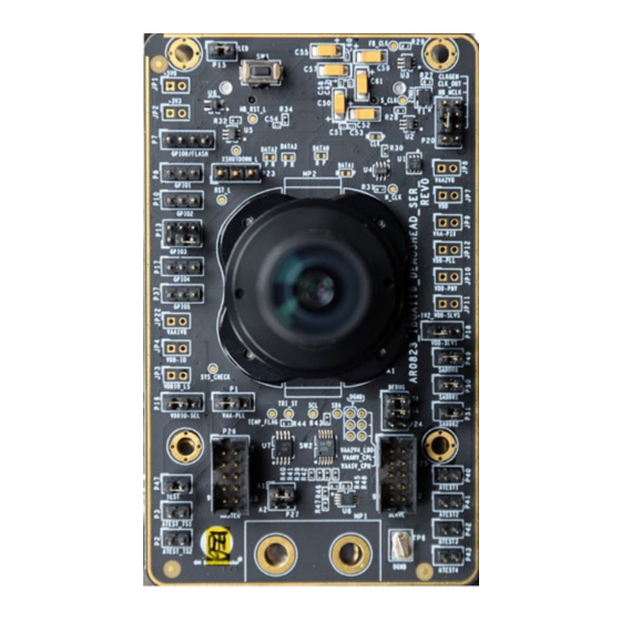
Figure 1. AR0823 iBGA116 Evaluation Board
1
www.onsemi.com
Publication Order Number:
EVBUM2860/D
Advertisement

Related Manuals for onsemi AR0823-IBGA116


Summary of Contents for onsemi AR0823-IBGA116
- Page 1 EVALUATION BOARD OVERVIEW The evaluation boards are designed to demonstrate the features of onsemi’s image sensor products. This headboard is intended to plug directly into the Demo3 system. Test points and jumpers on the board provide access to the clock, I/O’s, and other miscellaneous signals.
-
Page 2: Block Diagram
EVBUM2860/D BLOCK DIAGRAM Figure 2. Block Diagram www.onsemi.com... -
Page 3: Hardware Description
− +VDDIO_LS − − − − − − − − − − S_GPIO4 S_TEST S_GPIO0 − S_GPIO2 HB_RST_L S_GPIO3 S_GPIO1 − − − DEMO_SDA +2V8_VAA_HB +5V0_HB − − +1V8_HB DEMO_SCL HB_MCLK − +1V2_HB +3V3_HB +2V8_VDDIO_HB H_M_DATA0_P H_M_CLK_N H_M_DATA0_N H_M_CLK_P www.onsemi.com... - Page 4 TEST P47 ATEST2 P41 ATEST TS1 Sel P3 ATEST TS2 Sel P2 ATEST3 P42 EEPROM ADDR Sel P27 ATEST4 P43 Figure 3. Top View of Evaluation Board LED D1 Baseboard Connector J1 Figure 4. Bottom View of Evaluation Board www.onsemi.com...
- Page 5 Figure 6. Pin Locations and Assignments of Grouped Jumpers Left to Right Pin 1 Pins 1 and 2 Pins 3 and 4 Pins 5 and 6 Pins 7 and 8 Pins 9 and 10 Figure 7. Pin Locations and Assignments of Grouped Jumpers Top to Bottom www.onsemi.com...
- Page 6 3−5 Select Demo3 clock 2−4 Select Slave clock (for slave sensor in multi−camera mode) 6−8 Enable Master clock (to support slave sensor in multi−camera mode) XSHUTDOWN_L Open (Default) Normal operation 1−2 Reset controls XSHUTDOWN 2−3 Device in shutdown mode www.onsemi.com...
- Page 7 SW1 (Manual Reset Push Switch): ⇒ Push switch to activate the supervisory reset chip for a 240 ms low reset signal to the sensor. PRE−REQUISITES FOR BRING−UP • USB 3.0 cable and test computer • Latest version of Demo3 Baseboard • Latest version of DevWare software www.onsemi.com...
- Page 8 Interfacing to onsemi Demo3 Baseboard 3. Launch latest DevWare software on the test PC. The onsemi Demo3 baseboard has a similar 52−pin 4. When DevWare application starts, make sure “Load connector P5 which mates with J1 of the headboard. The Initialization Settings”...
- Page 9 Multimeter and Oscilloscope is required for these measurements. Probing Location and Default Jumper Setting The test points of interest are outlined in red and default jumper position in Green in Figure 9 below. Figure 9. Top View of the Board, Probing Locations Highlighted www.onsemi.com...
- Page 10 EVBUM2860/D Figure 10. Bottom View of the Board, Probing Locations Highlighted www.onsemi.com...
- Page 11 Clock Signal Check Using an oscilloscope, check the 27 MHz clock signals at TP8 (S_CLK) and TP9 (FB_CLK). These clock signals should oscillate at 1.8 V level. onsemi is licensed by the Philips Corporation to carry the I C bus protocol. www.onsemi.com...
-
Page 12: Additional Information
LIMITATIONS OF LIABILITY: onsemi shall not be liable for any special, consequential, incidental, indirect or punitive damages, including, but not limited to the costs of requalification, delay, loss of profits or goodwill, arising out of or in connection with the board, even if onsemi is advised of the possibility of such damages. In no event shall onsemi’s aggregate liability from any obligation arising out of or in connection with the board, under any theory of liability, exceed the purchase price paid for the board, if any.
Need help?
Do you have a question about the AR0823-IBGA116 and is the answer not in the manual?
Questions and answers