Table of Contents
Advertisement
Quick Links
AF0131 Smart iToF
Evaluation Board User's
Manual
EVBUM2868/D
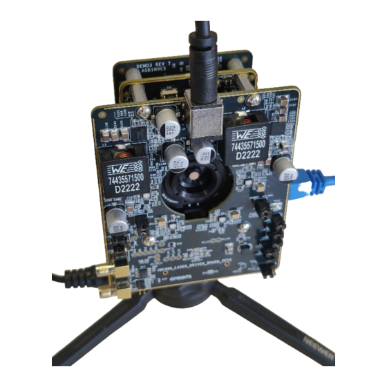
GENERAL OVERVIEW
This document is a manual for the setup and configuration of the
AF0131 Smart iToF depth sensor demo3 evaluation kit, see Figure 1.
Note that this setup concerns the sensor variant without depth
processing on−chip (AF0131 vs AF0130). This has consequences for
the software setup in DevwareX, operating frame rate as well as the
setup of the laser driver board. See specific sections for more details.
The sensor variants AF0130 & AF0131 are pin compatible.
FUNCTIONAL OVERVIEW
The demokit aims to show the performance and features of the
AF0131 Smart iToF depth sensor. DevwareX is the software used to
interface with the hardware over USB and configure the sensor in
different operating modes.
Two modes are currently available for evaluation:
1. Mode 2.2: 1.2 Mp, 15 fps, Single Frequency 100 MHz (range
0.3−1.5 m)
2. Mode 3.2: VGA, 15 fps, Dual Frequency 100 MHz + 120 MHz
(range 0.3−7.5 m)
As development progresses, more evaluation presets and
documentation will become available. Therefore MyON should be
checked regularly for the latest updates on this product. Please do
inform your onsemi representative in case you like to evaluate a mode
that is not yet available.
Please note that the kit has not (yet) been officially certified as eye
safe. However, several safety features have been implemented to
avoid any damage to the user's eyes, either by wrong configuration or
unexpected single fault failures. The exposure time of the sensor is
limited by the "Laser eye−safety monitoring" feature on the AF0131
sensor, which monitors the modulation of the lasers by the sensor.
Therefore, the lasers will turn off when the exposure time on the
sensor is set too high. On the VCSEL drivers, the over−current
protection and skin safety protection features are enabled and tested
as well.
ATTENTION: The emitted wavelength of the lasers is not visible to
the human eye! We advise the user to exercise caution
and follow the necessary guidelines to protect your
eyes from potential hazards.
© Semiconductor Components Industries, LLC, 2023
July, 2023 − Rev. 0
EVAL BOARD USER'S MANUAL
Figure 1. AF0131 Smart iToF Assembled
1
www.onsemi.com
Evaluation Board
Publication Order Number:
EVBUM2868/D
Advertisement
Table of Contents

Related Manuals for onsemi AF0131


Summary of Contents for onsemi AF0131
- Page 1 GENERAL OVERVIEW This document is a manual for the setup and configuration of the AF0131 Smart iToF depth sensor demo3 evaluation kit, see Figure 1. Note that this setup concerns the sensor variant without depth processing on−chip (AF0131 vs AF0130). This has consequences for the software setup in DevwareX, operating frame rate as well as the setup of the laser driver board.
- Page 2 REV7 + tripod stand & USB3 cable • Lens Mount: Demo to C−mount • Lens Adapter: C−mount to M18 x 0.35 • Lens Adapter: M18 x 0.35 to M6.9 x 0.25 • 4 mm Lens Extension Figure 2. Top View Sensor Headboard www.onsemi.com...
- Page 3 However, the drivers are currently still configured related Errata document Issue D. Figure 3. Top View Laser Driver Board Demo3 USB Interface Board For more info on the demo3 USB interface board, please refer to its user manual: https://www.onsemi.com/design/ tools−software/evaluation−board/agb1n0cs−gevk www.onsemi.com...
- Page 4 Demo Initialization should get you (0x4C) working with DevwareX. Your kit should come with up and running. The AF0131 only has the option to output correct version on demo3 for operating the AF0131 sensor RAW interleaved data on the main window. Therefore the and therefore the demo3 FPGA most probably does NOT plug−in should be started to show the calculated depth,...
- Page 5 Mode 2.2: ~7.5 m, 1280 x960 px Mode32_100MHz_120 Mode22_100MHz_11bit Mode 2.2: ~7.5 m, 640 x 480 px MHz_11bit Stream out Open the Plug−in Plug−in tab → iTof Depth Visualization Depth Enable Plug−in tab → iTof Depth Visualization Figure 5. Procedure of DevwareX Startup Wizard www.onsemi.com...
- Page 6 Several calibrations are necessary to show the optimal bias values for your system in the AF0130−REV1.ini file. performance of the sensor. For the AF0131 sensor variant, This is a one−time calibration needed for your system. these calibrations are applied off−chip, after Devware has Please have a look at the limitations of Four−Wire Serial...
- Page 7 These High Harmonics calibrations are not yet available Limited Frame Rate in the current hardware and software. Because the depth processing for AF0131 is done in The final version of the sensor will contain a 64 value software. The current version has a limitation on the frame Look−Up Table (LUT) for different modulation frequencies.
- Page 8 LIMITATIONS OF LIABILITY: onsemi shall not be liable for any special, consequential, incidental, indirect or punitive damages, including, but not limited to the costs of requalification, delay, loss of profits or goodwill, arising out of or in connection with the board, even if onsemi is advised of the possibility of such damages. In no event shall onsemi’s aggregate liability from any obligation arising out of or in connection with the board, under any theory of liability, exceed the purchase price paid for the board, if any.
Need help?
Do you have a question about the AF0131 and is the answer not in the manual?
Questions and answers