Advertisement
Quick Links
NCL31010 Evaluation Kit
User's Manual
IEEE 802.3bt Complete PoE Connected
LED Driver Power Solution Kit
NCL31010GEVK
General
The NCL31010GEVK kit allows easy implementation
and evaluation of a Power−over−Ethernet powered LED
Luminaire Controller that is able to operate with an assigned
power level up to 51 W.
The NCL31010REFGEVB evaluation board is based on
the Complete PoE Connected LED Driver Power Solution
NCL31010 (U2) with integrated PoE PD interface
controller, dual synchronous step−down DC/DC converters
for the main 3.3 V VDD system supply as well as an
auxiliary supply VDD2 and a current mode buck DC/DC
controller designed to operate as a LED driver.
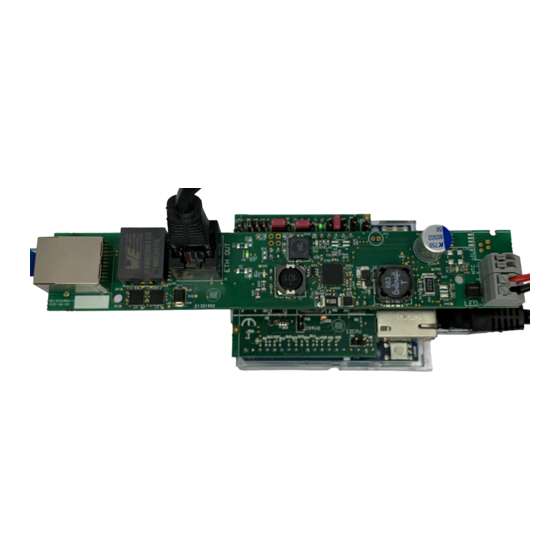
Figure 1. Operational NCL31010GEVK Showing
Basic Interconnections
The NCL31010REFGEVB board is designed as a PoE
splitter: having a PoE−enabled Ethernet port (labeled "PoE
IN") as input while passing through the data to another
Ethernet port (labeled "ETH OUT").
The NCL31010REFGEVB reference design board is
Ethernet Alliance PoE Certified and YellowDott ready.
© Semiconductor Components Industries, LLC, 2022
January, 2022 − Rev. 0
EVAL BOARD USER'S MANUAL
Quick Start Guide
Step 1: Mount the Arduino
unpowered microcontroller board with Arduino UNO
compatible headers.
Step 2: Configure the jumpers on the Arduino Adapter
Shield. Figure 2 shows the jumper settings for a
microcontroller board with Arduino UNO R3 compatible
headers using PWM for Analog Dimming.
Figure 2. Jumper Settings
Step 3: Mount the NCL31010REFGEVB on the Arduino
Adapter Shield (NCL31010AASGEVB).
Step 4: Connect the black Ethernet patch cable to the
Ethernet connector J1 (labeled "ETH OUT") and to the
Ethernet connector on the microcontroller board.
Step 5: Connect the LED load to connector J4 (labeled
"LED") while observing the correct polarity (cf. black and
red wires in the picture on the left). Ideally, the LED load has
a 0.65 A to 1.4 A current rating with a 16 V to 38 V forward
voltage range.
Step 6: Insert the Ethernet cable (cf. blue cable in the picture
on the left) coming from the PSE in the Ethernet connector
J2 (labeled "PoE IN").
If the PSE powers up the system, the green 3V3 VDD LED
should be ON and the orange MPS LED should be blinking.
The status of the remaining LEDs depends on the jumper
settings.
1
www.onsemi.com
®
Adapter Shield on the
Publication Order Number:
EVBUM2824/D
Advertisement

Related Manuals for onsemi NCL31010GEVK


Summary of Contents for onsemi NCL31010GEVK
- Page 1 LED Driver Power Solution Kit NCL31010GEVK General Quick Start Guide ® The NCL31010GEVK kit allows easy implementation Step 1: Mount the Arduino Adapter Shield on the and evaluation of a Power−over−Ethernet powered LED unpowered microcontroller board with Arduino UNO Luminaire Controller that is able to operate with an assigned compatible headers.
- Page 2 Autoclass whether it makes sense to go to the maximum The detection process can be easily corrupted by power state according to its assigned Class. equipment − connected to the NCL31010GEVK kit or the System Startup microcontroller board − that has a not high enough Once its port capacitance –...
- Page 3 NCL31010GEVK LED Driver Communication with NCL31010 is performed via the The LED driver is enabled when the LED_EN bit 1 in the C−bus on digital I/O pins D19/SCL and D18/SDA at the Control Register (&CTRL 0x04) is set. 7−bit address 80 (0x50), due to the 0E resistors mounted on The LED driver will regulate the LED current based on JP13 and JP14 on NCL31010REFGEVB.
- Page 4 NCL31010GEVK The table below shows the relationship between the DAC The table below shows the LED current and the DIM value, the DIM voltage and the LED current when using a voltage corresponding to some specific PWM duty cycle 12−Bit DAC with a 3.3 V Reference.
- Page 5 NCL31010GEVK Arduino Adapter Shield by placing a jumper on header P18 The temperature sensor on the LED module – if available or by mounting a 0E jumper on position R53 on the bottom − can be connected to NCL31010REFGEVB on connector side of the Arduino Adapter Shield.
- Page 6 The connection to the on−board PHY LAN8742A is via a Reduced Media−Independent Interface (RMII). Figure 3. Operational NCL31010GEVK on NUCLEO−F207ZG using PWM for Analog Dimming The user can remove the jumper from JP3 on the Don’t forget to mount the jumpers on both JP6 (CRS_DV) Nucleo−F207ZG to make sure the Nucleo−F207ZG only...
- Page 7 The connection to the on−board PHY LAN8742A is via a Reduced Media−Independent Interface (RMII). Figure 4. Operational NCL31010GEVK on NUCLEO−F207ZG using a DAC for Analog Dimming The user can remove the jumper from JP3 on the The reference input of the DAC is the VREF+ pin, which Nucleo−F207ZG to make sure the Nucleo−F207ZG only...
- Page 8 The connection to the KSZ8061 PHY Daughter Board is via a Reduced Media−Independent Interface (RMII). Figure 5. Operational NCL31010GEVK on SAM E54 Curiosity Ultra using PWM for Analog Dimming The development board has a Serial EEPROM and a Arduino Adapter Shield by mounting a jumper on P8. The...
- Page 9 The connection to the KSZ8061 PHY Daughter Board is via a Reduced Media−Independent Interface (RMII). Figure 6. Operational NCL31010GEVK on SAM E54 Curiosity Ultra using a DAC for Analog Dimming The development board has a Serial EEPROM and a An additional wire is required to connect the DAC output...
- Page 10 Serial Peripheral Interface (SPI) over the ICSP Header (Clock and Data) and the Arduino Interface (/SS). Figure 7. Operational NCL31010GEVK on Arduino UNO R3 and Arduino Ethernet Shield 2 The Arduino Ethernet Shield 2 generates an internal +3V3 Ethernet Shield 2 doesn’t drop below the W5500 Minimum supply from +5V with NX1117CE33Z (IC2) to power the Supply Voltage: i.e.
- Page 11 NCL31010GEVK Figure 8. Schematic Diagram NCL31010REFGEVB − NCL31010 www.onsemi.com...
- Page 12 NCL31010GEVK Figure 9. Schematic Diagram NCL31010REFGEVB − PoE Input and Adapter Shield Interface www.onsemi.com...
- Page 13 NCL31010GEVK Figure 10. Schematic Diagram NCL31010 Arduino Adapter Shield www.onsemi.com...
- Page 14 NCL31010GEVK ARDUINO is a registered trademark of Arduino SA. YellowDot is a trademark of Signify Holding B.V. All other brand names and product names appearing in this document are registered trademarks or trademarks of their respective holders. www.onsemi.com...
-
Page 15: Technical Support
LIMITATIONS OF LIABILITY: onsemi shall not be liable for any special, consequential, incidental, indirect or punitive damages, including, but not limited to the costs of requalification, delay, loss of profits or goodwill, arising out of or in connection with the board, even if onsemi is advised of the possibility of such damages. In no event shall onsemi’s aggregate liability from any obligation arising out of or in connection with the board, under any theory of liability, exceed the purchase price paid for the board, if any.
Need help?
Do you have a question about the NCL31010GEVK and is the answer not in the manual?
Questions and answers