Advertisement
Quick Links
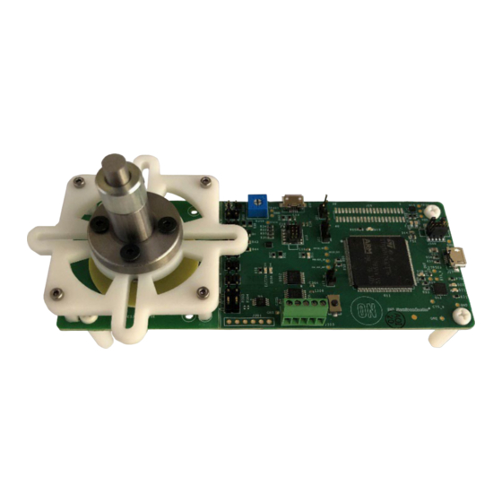
NCS32100 Rotary Inductive Position Sensor
Evaluation Board User Manual
STR-NCS32100-GEVK
INTRODUCTION
The STR−NCS32100−GEVK evaluation board provides
hardware and a PCB rotary sensor for full demonstration of
the NCS32100. The block diagram below shows the signal
path used to communicate with the NCS32100 through a
master controller. The NCS32100 is connected to a fully
functional PCB rotary sensor capable of sensing positions
with an accuracy of <±50 arcsec. The board can be
connected to a computer running the onsemi Strata
Application, which provides a user interface for accessing
position and velocity data, as well as a number of other
auxiliary features that will be explained in this quick start
guide.
Master Control Circuitry
USB
J10
JLINK OB
5 V
5 V
Regulator
USB
J17
FTDI Virtual
Serial COM
(STM32 MCU)
5 V
Figure 2. NCS32100 Inductive Rotary Position Sensor Evaluation Board Block Diagram
The NCS32100 evaluation board houses a full rotary
sensor application with a master controller for accessing
position and velocity data. Data is displayed through the
onsemi Strata application (available for download from
© Semiconductor Components Industries, LLC, 2022
July, 2022 − Rev. 0
3.3 V
Adjustable
Regulator
RS485
Tranceiver
Level
Master
Shifter
Figure 1. NCS32100 Evaluation Board
NCS32100 Application Circuitry
RS485
NCS32100
Tranceiver
Module
Connector
onsemi.com). The evaluation board is programmed,
calibrated, and ready for demonstration. This quick start
guide will explain how to connect the evaluation board for
plug and play evaluation.
1
USER MANUAL
www.onsemi.com
PCB
Stator
PCB
Rotor
Publication Order Number:
UM70073/D
Advertisement

Related Manuals for onsemi STR-NCS32100-GEVK


Summary of Contents for onsemi STR-NCS32100-GEVK
- Page 1 PCB rotary sensor capable of sensing positions with an accuracy of <±50 arcsec. The board can be connected to a computer running the onsemi Strata Application, which provides a user interface for accessing position and velocity data, as well as a number of other auxiliary features that will be explained in this quick start Figure 1.
- Page 2 NCS32100 over the RS−485 interface. The STM 32 MCU also communicates data to an external computer via a virtual Serial COM port. Application is plug and play with the onsemi Strata App. • Evaluation board has been configured and calibrated to work with the attached 40mm Pre−Calibrated...
-
Page 3: Quick Start Procedure
STR−NCS32100−GEVK QUICK START PROCEDURE 1. Download the onsemi Strata Application. The latest 2. Connect computer running the onsemi Strata Application to the evaluation board (U17 → Strata release is available for download from www.onsemi.com/support/strata−developer−studio highlighted in blue in the image below) using the provided USB cable. - Page 4 The current position and velocity the NCS32100. The right side of the window has a outputs are also shown near the bottom of the variety of diagnostics. www.onsemi.com...
- Page 5 NCS32100 by dialing the blue R350 potentiometer. Turning the potentiometer clockwise will lower the VBAT voltage Over Speed (see Battery Backup Mode section). The ‘Over speed’ indicator will turn red if the velocity of the rotor exceeds 6,000 rpm. www.onsemi.com...
- Page 6 500 rpm. While the rotor is spinning, click the “Calibrate” button, and the UI will freeze while the calibration routine runs. Once the calibration routine has completed, the UI will return to normal operation. www.onsemi.com...
- Page 7 They can also use the evaluation board (Shaft Diameter) master to communicate with a separated sensor module that can be connected to a motor or system shaft with a coupler using the provided mounting holes. Figure 12. Rotor Fixture Dimensions www.onsemi.com...
- Page 8 Manual. The reference design manual defines supporting used. Users should also note that the sensor module on the circuitry needs, sensor connection information, evaluation board is assembled with materials that will configuration details, and interface protocol details. Figure 13. NCS32100 Connection Schematic www.onsemi.com...
- Page 9 Strata UI. In (with GND, VBAT, and VCC) to an external cable if desired. Figure 14. Master Side RS−485 Transceiver and Level Shifters Figure 15. Master Controller MCU for Strata UI Interface www.onsemi.com...
- Page 10 All operating parameters, including “Typicals” must be validated for each customer application by customer’s technical experts. onsemi does not convey any license under any of its intellectual property rights nor the rights of others. onsemi products are not designed, intended, or authorized for use as a critical component in life support systems or any FDA Class 3 medical devices or medical devices with a same or similar classification in a foreign jurisdiction or any devices intended for implantation in the human body.
Need help?
Do you have a question about the STR-NCS32100-GEVK and is the answer not in the manual?
Questions and answers