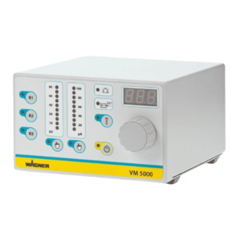
WAGNER VM 5000 Operating Manual
Hide thumbs
Also See for VM 5000:
- Translation of the original operating manual (56 pages) ,
- Operating manual (48 pages)

Related Manuals for WAGNER VM 5000


Summary of Contents for WAGNER VM 5000
- Page 1 Translation of the Original Operating Manual VM 5000 Version 08/2014 Electrostatic Control Unit for Electrostatic Manual Spray Guns B_03269 II 3 G...
-
Page 3: Table Of Contents
4.1.1 Electrical Equipment 4.1.2 Staff Qualifi cations 4.1.3 Safe Work Environment Safety Instructions for Staff 4.2.1 Safe Handling of WAGNER Spray Devices 4.2.2 Grounding the Device 4.2.3 Product Hoses 4.2.4 Cleaning and Flushing 4.2.5 Handling Hazardous Liquids, Lacquers and Paints 4.2.6... - Page 4 Check the Control Unit for Leak-Tightness DISPOSAL ACCESSORIES SPARE PARTS 13.1 How Can Spare Parts Be Ordered? 13.2 Control unit VM 5000 WARRANTY AND CONFORMITY DECLARATIONS 14.1 Important Notes Regarding Product Liability 14.2 Warranty Claim 14.3 CE Declaration of Conformity 14.4...
-
Page 5: About This Manual
VM 5000 EDITION 08/2014 ORDER NUMBER DOC2318718 OPERATING MANUAL ABOUT THIS MANUAL PREFACE The operating manual contains information about safely operating, maintaining, cleaning and repairing the device. The operating manual is part of the device and must be available to operating and service staff . -
Page 6: Languages
VM 5000 EDITION 08/2014 ORDER NUMBER DOC2318718 OPERATING MANUAL LANGUAGES The VM 5000 operating manual is available in the following languages: Language Order No. Language Order No. German 2310484 English 2318718 French 2318719 Italian 2318720 Spanish 2318721 Additional languages on request or at:... -
Page 7: Terminology For The Purpose Of This Manual
VM 5000 EDITION 08/2014 ORDER NUMBER DOC2318718 OPERATING MANUAL TERMINOLOGY FOR THE PURPOSE OF THIS MANUAL Cleaning Manual cleaning of devices and device parts with cleaning agents Flushing Internal fl ushing of ink-guiding parts with fl ushing agent Staff qualifi cations... -
Page 8: Correct Use
GM 5000EA or GM 5000EAC spray guns used to apply liquid coating media and the high-voltage Universal cascade. The VM 5000 may only be operated together with the above-mentioned manual spray guns or the high-voltage Universal cascade. If the control unit is operated in combination with devices other than the above-mentioned spray guns, the SIRA authorization (type approval) ceases to be valid. -
Page 9: Use In Potentially Explosive Areas
1 and the control unit in the zone 2 area. (See Chapter 3 "Explosion Protection Identifi cation".) If the Wagner high-voltage Universal cascade is operated in connection with the VM 5000 control unit, the high-voltage cascade cannot be used in an Ex zone. However, the control unit may be still used in the zone 2 area. -
Page 10: Reasonably Foreseeable Misuse
VM 5000 EDITION 08/2014 ORDER NUMBER DOC2318718 OPERATING MANUAL REASONABLY FORESEEABLE MISUSE The forms of misuse listed below may result in physical injury or property damage: Use with non-authorized spray guns: Coating work pieces which are not grounded; Performing unauthorized conversions or modifi cations to the device;... -
Page 11: Identification
The control unit is designed together with the spray gun in accordance with the 94/9/EC (ATEX) directive. The spray gun is suitable for use in potentially explosive areas in zone 1 and the control unit in the zone 2 area. VM 5000 control unit European Communities Notifi ed body: PTB... -
Page 12: Identification "X
Only the corresponding cables for the device may be used (see chapter 12 and operating manual for the spray gun). Permissible Device Combinations The following spray guns may be connected to the VM 5000 control unit: - Spray gun GM 5000EA - Spray gun GM 5000EAC... -
Page 13: Type Plate
VM 5000 EDITION 08/2014 ORDER NUMBER DOC2318718 OPERATING MANUAL TYPE PLATE II 3 G Main Switch Ex nR IIA T4 Gc II (2) G 0102 SIRA 11 ATEX 5374X Prim. Spannung: max. 20Vpp 1.0 AT Voltage: J. WAGNER AG Industriestrasse 22 Strom: max. -
Page 14: General Safety Instructions
VM 5000 EDITION 08/2014 ORDER NUMBER DOC2318718 OPERATING MANUAL GENERAL SAFETY INSTRUCTIONS SAFETY INSTRUCTIONS FOR THE OPERATOR Keep this operating manual on hand near the device at all times. Always follow local regulations concerning occupational safety and accident prevention. 4.1.1... -
Page 15: Safety Instructions For Staff
If necessary, or at least every 12 months, the liquid ejection devices should be checked by an expert (e.g. Wagner service technician) to ensure their safe operational condition in accordance with the guidelines for liquid ejection devices (ZH 1/406 and BGR 500 Part 2 Chapter 2.29 and 2.36). -
Page 16: Grounding The Device
VM 5000 EDITION 08/2014 ORDER NUMBER DOC2318718 OPERATING MANUAL Carry out the work steps as described in the "Pressure Relief" chapter: - If pressure relief is required. - If the spraying work is interrupted or stopped. - Before the device is cleaned on the outside, checked or serviced. -
Page 17: Product Hoses
VM 5000 EDITION 08/2014 ORDER NUMBER DOC2318718 OPERATING MANUAL 4.2.3 PRODUCT HOSES Ensure that the hose material is chemically resistant to the sprayed products and the fl ushing agents used. Ensure that the product hose is suitable for the pressure generated. -
Page 18: Handling Hazardous Liquids, Lacquers And Paints
VM 5000 EDITION 08/2014 ORDER NUMBER DOC2318718 OPERATING MANUAL When commissioning or emptying the device, please note that an explosive mixture may temporarily exist inside the lines and components of equipment: - depending on the coating product used, - depending on the fl ushing agent (solvent) used, explosive mixture inside the lines and items of equipment. -
Page 19: Touching Hot Surfaces
VM 5000 EDITION 08/2014 ORDER NUMBER DOC2318718 OPERATING MANUAL 4.2.6 TOUCHING HOT SURFACES Only touch hot surfaces if you are wearing protective gloves. When operating the device with a coating product with a temperature of > 43 °C; 109 °F: - Identify the device with a warning label, "Warning – Hot surface". -
Page 20: Description
Additionally, the VM 5000 control unit can be used as a universal high-voltage generator, in combination with the high-voltage Universal cascade. In addition, the VM 5000 control unit has a wide range of other functions, such as an operating hours counter, service interval display, external approval, fault display and an easy-to-use interface. -
Page 21: Technical Data
VM 5000 EDITION 08/2014 ORDER NUMBER DOC2318718 OPERATING MANUAL TECHNICAL DATA Input voltage 115 VAC - 230 VAC, 50 Hz / 60 Hz Input power max. 40 W Input current max. 0.5 A Output voltage max. 20 Vpp Output current max. -
Page 22: Operating Elements And Connections
VM 5000 EDITION 08/2014 ORDER NUMBER DOC2318718 OPERATING MANUAL OPERATING ELEMENTS AND CONNECTIONS 5.5.1 OPERATING ELEMENTS FRONT SIDE 1 Push button "Recipe 1" 2 Push button "Recipe 2" 3 Push button "Recipe 3" 4 Illuminated display "R1" Lights up if recipe 1 is used. - Page 23 VM 5000 EDITION 08/2014 ORDER NUMBER DOC2318718 OPERATING MANUAL μA VM 5000 B_03271 15 LED display: 7 segments, three-digit number Displays set values and actual values for high-voltage and for the spray current Display showing error number in the event of warnings and malfunctions...
-
Page 24: Connections On The Rear Side
Warning - Do not disconnect under voltage. 27 Interface Warning - Do not disconnect under voltage. 28 Cover of the interface connection 29 Cover of the service connection Only for WAGNER service personnel 30 Knurled nut grounding Grounding cable connection to the signal ground... -
Page 25: Assembly And Commissioning
VM 5000 EDITION 08/2014 ORDER NUMBER DOC2318718 OPERATING MANUAL ASSEMBLY AND COMMISSIONING TRAINING ASSEMBLY/COMMISSIONING STAFF WARNING Incorrect installation/operation! Risk of injury and damage to the device. The assembly and commissioning staff must have the technical skills to safely undertake commissioning. -
Page 26: Additional Components
2 for the compressed air 4 Grounding cable to the signal supply ground The operation of the VM 5000 in combination with the high-voltage Universal cascade is described in detail in the operating manual of the high-voltage Universal cascade. WARNING Incorrect installation/operation! Risk of injury and damage to the device. -
Page 27: Location Of The Control Unit
VM 5000 EDITION 08/2014 ORDER NUMBER DOC2318718 OPERATING MANUAL NOTICE Impurities in the spraying system! Spray gun blockage, products harden in the spraying system. Flush the spray gun and paint supply with a suitable fl ushing agent. LOCATION OF THE CONTROL UNIT... -
Page 28: Grounding
VM 5000 EDITION 08/2014 ORDER NUMBER DOC2318718 OPERATING MANUAL GROUNDING It is important for systems safety and to achieve an optimum coating that all system components such as work pieces, conveyors, paint supply, control unit and booth or spraying stand are perfectly grounded. - Page 29 VM 5000 EDITION 08/2014 ORDER NUMBER DOC2318718 OPERATING MANUAL Grounding scheme (example) Conveyor Control unit Grounding Work piece cable Product supply R max < 1 MΩ Paint tank Spraying stand Floor, static dissipative B_03234 Minimum cable cross-section Control unit Product supply...
-
Page 30: Example, Aircoat Spraying System
18 Tank for return fl ow Sliding table 12 Air pressure regulator 19 Paint tank Air pressure regulator + air fi lter 13 VM 5000 control unit 20 Tank for fl ushing agent Product suction system 14 Protective hose 21 Mains cable... -
Page 31: Verifying A Safe Operational Condition
Lay grounding cable from the grounding screw on the device to the signal ground and ensure that all other conductive parts within the working area are grounded. Connect the VM 5000 electrostatic control unit via the mains cable to the socket interlocked with the extraction system. -
Page 32: Operation
VM 5000 EDITION 08/2014 ORDER NUMBER DOC2318718 OPERATING MANUAL OPERATION TRAINING THE OPERATING STAFF WARNING Incorrect operation! Risk of injury and damage to the device. The operating staff must be qualifi ed and fi t to operate the entire system. -
Page 33: Emergency Deactivation
VM 5000 EDITION 08/2014 ORDER NUMBER DOC2318718 OPERATING MANUAL DANGER High-voltage fi eld! Danger to life from malfunction of heart pacemaker Make sure that persons with pacemakers: Do not work with the electrostatic spray gun. Do not enter the high-voltage area. -
Page 34: Setting And Saving Recipes
VM 5000 EDITION 08/2014 ORDER NUMBER DOC2318718 OPERATING MANUAL 4. The control unit is ready for operation. Note: μA Each starting sequence is concluded by allocating the saved set data in recipe "R1". VM 5000 B_03682 SETTING AND SAVING RECIPES Set values for the high-voltage (kV) and for the spray current limitation (μA) are stored in... -
Page 35: Setting The High-Voltage
VM 5000 EDITION 08/2014 ORDER NUMBER DOC2318718 OPERATING MANUAL 7.4.1 SETTING THE HIGH-VOLTAGE Procedure: 1. Press the "High-voltage" button (21) to adjust the high-voltage. μA The LED (22) indicates that high- voltage is selected. VM 5000 B_03682 22 21 2. The high-voltage can now be... -
Page 36: Setting The Current Limitation
VM 5000 EDITION 08/2014 ORDER NUMBER DOC2318718 OPERATING MANUAL 7.4.2 SETTING THE CURRENT LIMITATION Procedure: 1. Press the "Current Limitation" button (19) to adjust the limitation of the spray current. μA The LED (20) indicates that current limitation is selected. -
Page 37: Display During Spraying
VM 5000 EDITION 08/2014 ORDER NUMBER DOC2318718 OPERATING MANUAL 7.4.3 DISPLAY DURING SPRAYING Ready to spray using R2 recipe. See fi gure below. Control unit in ready position. The LEDs for the set values light up in a dot arrangement and the value for high-voltage is displayed in digits. -
Page 38: Standby Mode
VM 5000 EDITION 08/2014 ORDER NUMBER DOC2318718 OPERATING MANUAL STANDBY MODE If you want to spray without high-voltage, select the standby mode. Press push button (17) briefl y and the "Standby" illuminated display (18) lights up. All the other LEDs go out. -
Page 39: Display "Perform Service
VM 5000 EDITION 08/2014 ORDER NUMBER DOC2318718 OPERATING MANUAL DISPLAY "PERFORM SERVICE" μA VM 5000 B_03682 Prerequisite: The function "Maintenance interval limit" is activated. "Servicing the spray gun" Once the time for the defi ned maintenance interval has expired, the LED display (13) starts to fl ash. -
Page 40: Device Configuration
Overview of the device confi guraton levels: There are 3 levels: Level 1: for operator Level 2: for WAGNER Service Level 3: for WAGNER production plant 7.7.1 PARAMETER OVERVIEW OF LEVEL 1 FOR USERS Parameter Value Description C11 External release off (factory setting) The device functions as a standalone device. - Page 41 VM 5000 EDITION 08/2014 ORDER NUMBER DOC2318718 OPERATING MANUAL C14 Operation mode off (factory setting) Operation with GM 5000EA or GM 5000EAC manual spray gun This parameter Electrostatic automatic spray gun is linked to High-voltage Universal 3 G cascade parameter C11.
- Page 42 VM 5000 EDITION 08/2014 ORDER NUMBER DOC2318718 OPERATING MANUAL...
-
Page 43: Access To The Device Configuration Mode
VM 5000 EDITION 08/2014 ORDER NUMBER DOC2318718 OPERATING MANUAL 7.7.2 ACCESS TO THE DEVICE CONFIGURATION MODE Procedure: 1. Switch to "Standby" by pressing the "Standby" μA button (17). The orange LED "Standby" (18) lights up. VM 5000 B_03682 2. Press and hold the "Service"... -
Page 44: Setting Example "Parameter C11
For ease of operation the confi guration settings are divided into three groups. The fi rst group is for the end user, the other two groups are password protected and reserved for Wagner Service and the Wagner production sites or the Wagner Service Center, which have the necessary infrastructure. - Page 45 VM 5000 EDITION 08/2014 ORDER NUMBER DOC2318718 OPERATING MANUAL μA VM 5000 B_03682 21 20 The fl ashing LED display (13) indicates that the parameter value "oFF" in the display (15) can be changed with the universal control dial (16). Possible values in C11 are "on" or "oFF".
-
Page 46: Operating Hours Counter/Service Display
VM 5000 EDITION 08/2014 ORDER NUMBER DOC2318718 OPERATING MANUAL OPERATING HOURS COUNTER/SERVICE DISPLAY Two hour counters are integrated into the control unit. The absolute counter measures the ongoing hours of operation of the spray gun and maintenance intervals for the spray gun can therefore be determined and monitored with the maintenance hours counter. -
Page 47: Maintenance Counter Set Up And Reading
VM 5000 EDITION 08/2014 ORDER NUMBER DOC2318718 OPERATING MANUAL 7.8.1 MAINTENANCE COUNTER SET UP AND READING When using the device for the fi rst time, the function for the maintenance hours counter is deactivated. This function can be activated with the "R3" push button (3). The maintenance interval limit can be set within a range of 0 to 999 hours. -
Page 48: External Interface
VM 5000 EDITION 08/2014 ORDER NUMBER DOC2318718 OPERATING MANUAL EXTERNAL INTERFACE The control unit is equipped with an interface. Before using it, you have to select the respective parameters in the device confi guration. External release Control unit GND >> Release... - Page 49 VM 5000 EDITION 08/2014 ORDER NUMBER DOC2318718 OPERATING MANUAL Designation Description External release Potential-free contact between pin 1 and pin 8 (ground) - Closed Release issued - Open Release not issued Fault reset Potential-free contact (button) between pin 2 and pin 8 (ground) - If there is a fault, it can be acknowledged by pressing a button.
-
Page 50: Cleaning And Maintenance
DANGER Incorrect maintenance/repair! Danger to life and damage to the device. Only a WAGNER service center or a suitably trained person may carry out repairs and replace parts. Only repair and replace parts that are listed in the "Spare Parts"... - Page 51 VM 5000 EDITION 08/2014 ORDER NUMBER DOC2318718 OPERATING MANUAL Cleaning the control unit If there are deposits on the surfaces, the device may form electrostatic charges. Flames or sparks can form during discharge. Remove deposits from the surfaces to maintain conductivity.
-
Page 52: Maintenance
In accordance with the guideline for liquid ejection devices (ZH 1/406 and BGR 500 Part 2 Chapter 2.29 and Chapter 2.36): - The liquid ejection devices should be checked by an expert (e.g. WAGNER service technician) to ensure their safe operational condition as required and at least every 12 months. -
Page 53: Safety Checks
DIN EN 60079-15:2011 have to be fulfi lled. This inspection may only be carried out by a skilled person or by trained WAGNER service personnel. When carrying out the leakage tightness test, the mains input terminal serves as a test port. -
Page 54: Troubleshooting And Rectification
VM 5000 EDITION 08/2014 ORDER NUMBER DOC2318718 OPERATING MANUAL TROUBLESHOOTING AND RECTIFICATION Functional fault Cause Remedy No illuminated display lights - Mains supply not switched on. - Check and switch on mains supply - Fuses defective - Replace fuses - Wagner Service... - Page 55 VM 5000 EDITION 08/2014 ORDER NUMBER DOC2318718 OPERATING MANUAL The fault LED (12) indicates faults. In addition, the error number is shown in the 7-segment display (15). If a fault occurs, the high voltage is immediately switched off . The user can only continue to work once the fault has been remedied and acknowledged with push button for service (14).
-
Page 56: Repair Work
In accordance with the guideline for liquid ejection devices (ZH 1/406 and BGR 500 Part 2 Chapter 2.29 and Chapter 2.36): - The liquid ejection devices should be checked by an expert (e.g. WAGNER service technician) to ensure their safe operational condition as required and at least every 12 months. -
Page 57: Disposal
WAGNER or one of our dealers will take back your used WAGNER electric or electronic equipment and will dispose of it for you in an environmentally-friendly manner. -
Page 58: Accessories
264626 Mains cable USA 2 m; 6.6 ft 264625 Mains cable Japan 3 m; 9.8 ft 2317600 Interface cable VM 5000, 10 m; 32.8 ft 130215 Grounding cable 10 m; 32.8 ft 264332 Grounding cable, complete 0.75 m; 2.5 ft... -
Page 59: Spare Parts
DANGER Incorrect maintenance/repair! Danger to life and damage to the device. Only a WAGNER service center or a suitably trained person may carry out repairs and replace parts. Only repair and replace parts that are listed in the "Spare Parts"... -
Page 60: Control Unit Vm 5000
VM 5000 EDITION 08/2014 ORDER NUMBER DOC2318718 OPERATING MANUAL 13.2 CONTROL UNIT VM 5000 B_03286... - Page 61 VM 5000 EDITION 08/2014 ORDER NUMBER DOC2318718 OPERATING MANUAL Spare parts list for VM 5000 control unit Order No. Designation 2310477 VM 5000 control unit 9903312 Recessed head raised fi llister head screw, H form 9952593 Protection cap for device socket...
-
Page 62: Warranty And Conformity Declarations
The manufacturer will not be held liable or will only be held partially liable if third-party accessories or spare parts have been used. With genuine WAGNER accessories and spare parts, you have the guarantee that all safety regulations are complied with. -
Page 63: Ce Declaration Of Conformity
Spray gun: CE Certifi cate of Conformity The CE certifi cate of conformity is enclosed with this product. If needed, further copies can be ordered through your WAGNER dealer by specifying the product name and serial number. Order number: 2310487... -
Page 64: Notes On National Regulations And Guidelines
VM 5000 EDITION 08/2014 ORDER NUMBER DOC2318718 OPERATING MANUAL 14.4 NOTES ON NATIONAL REGULATIONS AND GUIDELINES Technical rule for operating safety Part 2, Chapter 2.36 Working with Liquid Ejection Devices Part 2, Chapter 2.29 Working with Coating Products Avoiding ignition risks... - Page 65 VM 5000 EDITION 08/2014 ORDER NUMBER DOC2318718 OPERATING MANUAL...
- Page 66 VM 5000 EDITION 08/2014 ORDER NUMBER DOC2318718 OPERATING MANUAL...
- Page 67 VM 5000 EDITION 08/2014 ORDER NUMBER DOC2318718 OPERATING MANUAL...
- Page 68 Order No. 2318718 Edition 08/2014 Germany Phone E-mail Switzerland Phone More contact addresses on the internet at: Company/Locations/WAGNER worldwide Subject to changes without notice...
Need help?
Do you have a question about the VM 5000 and is the answer not in the manual?
Questions and answers