WAGNER VM 5000 Operating Manual
Electrostatic control unit for electrostatic hand spray guns
Hide thumbs
Also See for VM 5000:
- Translation of the original operating manual (56 pages) ,
- Operating manual (68 pages)

Related Manuals for WAGNER VM 5000


Summary of Contents for WAGNER VM 5000
- Page 1 Translation of the original Operating manual VM 5000 Edition 03/2012 Electrostatic control unit for electrostatic hand spray guns B_03269 II 3 G (in submission)
-
Page 3: Table Of Contents
Safety instructions for the operator 2.1.1 Electrical equipment 2.1.2 Personnel qualifi cations 2.1.3 A safe work environment Safety instructions for staff 2.2.1 Safe handling of WAGNER spray units 2.2.2 Earth the unit 2.2.3 Material hoses 2.2.4 Cleaning 2.2.5 Handling hazardous liquids, varnishes and paints 2.2.6... - Page 4 Setting the high-voltage 6.2.2 Setting the current limiting 6.2.3 Spray display Standby mode „Conduct service“ display TROUBLE SHOOTING AND SOLUTION MAINTENANCE AND REPAIR Maintenance Repair PRODUCT DISPOSAL ACCESSORIES SPARE PARTS 11.1 How to order spare parts? 11.2 VM 5000 spare parts list...
-
Page 5: About These Instructions
VM 5000 EDITION 03/2012 2318718 PART NUMBER DOC OPERATING MANUAL ABOUT THESE INSTRUCTIONS LANGUAGES 2310484 2318718 2318719 2318720 2318721 WARNINGS, NOTES AND SYMBOLS IN THESE INSTRUCTIONS Warning instructions in this manual point out particular dangers to users and equipment and state measures for avoiding the hazard. -
Page 6: General Safety Instructions
VM 5000 EDITION 03/2012 2318718 PART NUMBER DOC OPERATING MANUAL GENERAL SAFETY INSTRUCTIONS SAFETY INSTRUCTIONS FOR THE OPERATOR Keep these operating instructions to hand near the unit at all times. Always follow local regulations concerning occupational safety and accident prevention. -
Page 7: Safety Instructions For Staff
Always follow local regulations concerning occupational safety and accident prevention. 2.2.1 SAFE HANDLING OF WAGNER SPRAY UNITS The spray jet is under pressure and can cause dangerous injuries. Avoid injection of paint or cleaning agents: Never point the spray gun at people. -
Page 8: Cleaning
VM 5000 EDITION 03/2012 2318718 PART NUMBER DOC OPERATING MANUAL 2.2.4 CLEANING De-energize the unit electrically. Disconnect the pneumatic supply line. Relieve the pressure from the unit. Ensure that the flash point of the cleaning agent is at least 15K above the ambient tem- perature. -
Page 9: Correct Use
VM 5000 EDITION 03/2012 2318718 PART NUMBER DOC OPERATING MANUAL CORRECT USE SAFETY-RELEVANT INFORMATION ABOUT DISCHARGES The plastic parts of the spray gun are charged electrostatically by the high-voltage field of the spray pistol. Harmless discharges (brush discharges) are possible after contact with plastic parts. -
Page 10: Use In An Explosion Hazard Area
2.5.1 CORRECT USE The VM 5000 control unit may only be used in combination with the GM 5000EA or GM 5000EAC hand spray guns. If the control unit is operated in combination with devices other than the above-mentioned spray guns, the SIRA and FM authorizations (type approvals) cease to apply. -
Page 11: Explosion Protection According To Fm
VM 5000 EDITION 03/2012 2318718 PART NUMBER DOC OPERATING MANUAL The „Gas-proof“ type of explosion protection is only guaranteed if all sealed elements in the control unit are available and undamaged. During operation, all electric connections in the control unit and relevant plug connectors or shut-off devices have to be tightly sealed. -
Page 12: Guarantee And Conformity Declarations
fitted , operated and maintained. If other makes of accessory and spare parts are used, the manufacturer‘s liability could be fully or partially null and void. The usage of original WAGNER accessories and spare parts guarantees that all safety regulations are observed. GUARANTEE CLAIM... -
Page 13: Ce-Conformity
II 2 G EEx 0.24mJ 0102 SIRA 11 ATEX 5374X CE Certificate of Conformity The certificate is enclosed with this product. The certificate of conformity can be reordered from your WAGNER representative, quoting the product and serial number. Part number : 2310487... -
Page 14: Description
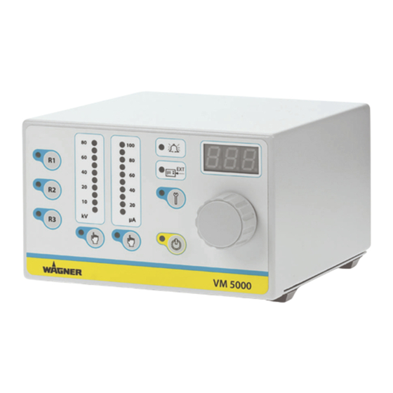
DESCRIPTION FIELDS OF APPLICATION, USING IN ACCORDANCE WITH THE INSTRUCTIONS WAGNER‘s electrostatic control unit VM 5000 controls the high voltage supply to the spray guns used to apply liquid coating media GM 5000EAC and GM 5000EA. The VM 5000 may only be operated together with the above-mentioned hand spray guns. -
Page 15: Technical Data
VM 5000 EDITION 03/2012 2318718 PART NUMBER DOC OPERATING MANUAL TECHNICAL DATA Input voltage 115 VAC - 230 VAC, 50 Hz / 60 Hz Input power max. 40 W Input current max. 0.5 A Output voltage max. 20 Vpp Output current max. -
Page 16: Functional Description
(or to earth) the high-voltage is reduced automatically to prevent an accidental spark discharge. In addition, the VM 5000 control unit has a wide range of other functions, such as an operating hours counter, service interval display, external approval, fault display and an easy-to-use interface. - Page 17 VM 5000 EDITION 03/2012 2318718 PART NUMBER DOC OPERATING MANUAL μA VM 5000 B_03271 11 Illuminated display: External release 12 Illuminated display: Fault 13 Illuminated display: Service 14 Push button: Service 15 Display LED, 7 segments, three-digit number Indicates the target and actual values of high-voltage and spray voltage.
-
Page 18: Connections On The Rear Side
Warning - Do not disconnect under voltage. 27 Interface Warning - Do not disconnect under voltage. 28 Cover of the interface connections 29 Cover of the service connections For Wagner service personnel only! 30 Knurled nut earthing Earthing cable connection to the system earth. -
Page 19: Preparation Before Starting Work
(see WAGNER accessories). Spray guns that are compatible with the VM 5000: AirCoat-Spray GM 5000EACR or GM 5000EACF Air-Spray GM 5000EAR or GM 5000EAF... -
Page 20: Positioning Of The Unit
VM 5000 EDITION 03/2012 2318718 PART NUMBER DOC OPERATING MANUAL POSITIONING OF THE UNIT DANGER Incorrect installation of the unit! Risk of explosion and equipment damage Place the unit outside the spray booth/zone. Place the unit, if possible, outside the explosion zone (Positioning in explosion zone 2 is enables). - Page 21 VM 5000 EDITION 03/2012 2318718 PART NUMBER DOC OPERATING MANUAL WARNING Heavy paint mist if earthing is insufficient! Risk of poisoning Insufficient paint application quality Earth all unit components. Earth the workpieces being painted. SIHI_0003_GB The imperfect earthing of a work piece will result in: •...
-
Page 22: Example For Aircoat Spraying System
Compressed air connection Return valve Pneumatic pump Stop valve Container for return fl ow Carriage Air pressure regulator Paint container Pressure regulator + VM 5000 control unit Container, cleaning agent air fi lter Protective hose Mains cable Material suction system... - Page 23 ➞ Lay earthing cable from the earthing screw on the device to the signal ground and ensure that all other conductive parts within the area of work are earthed. ➞ Connect the VM 5000 electrostatic control unit via the mains cable to the socket interlocked with the extraction system.
-
Page 24: Device Configuration
VM 5000 EDITION 03/2012 2318718 PART NUMBER DOC OPERATING MANUAL DEVICE CONFIGURATION 5.5.1 OVERVIEW OF PARAMETERS Parameters Values Description C11 Remote-release The device functions as a standalone device. External (factory setting) approval by interface does not have to be defi ned. The bypass is activated. -
Page 25: Access To The Device Configuration Mode
VM 5000 EDITION 03/2012 2318718 PART NUMBER DOC OPERATING MANUAL 5.5.2 ACCESS TO THE DEVICE CONFIGURATION MODE Works procedure: 1. Switch „Standby“ μA pressing the „Standby“ key (17). The orange LED „Standby“ (18) lights up. VM 5000 B_03682 2. Press push button „Service“ (14) and hold it down. -
Page 26: Setting Example „Parameter C11
For ease of operation the confi guration settings are divided into three groups. The fi rst group is for the end user, the other both groups, protected by a password, are reserved for Wagner Service and the Wagner production sites or the Wagner Service Center, which have the necessary infrastructure. - Page 27 VM 5000 EDITION 03/2012 2318718 PART NUMBER DOC OPERATING MANUAL μA VM 5000 B_03682 21 20 The fl ashing LED display (13) indicates that the parameter value, „oFF“ in the display (15) can be changed by the universal control dial (16). Possible values in C11 are „on“ or „oFF“.
-
Page 28: Operating Hours Counter/Warning Display
VM 5000 EDITION 03/2012 2318718 PART NUMBER DOC OPERATING MANUAL OPERATING HOURS COUNTER/WARNING DISPLAY 2 hour counters are integrated into the control unit. The absolute counter measures the ongoing hours of operation of the spray gun and with the service hours counter, service intervals can be determined and monitored for the spray gun. -
Page 29: Set Up And Query Service Counter
VM 5000 EDITION 03/2012 2318718 PART NUMBER DOC OPERATING MANUAL 5.6.1 SET UP AND QUERY SERVICE COUNTER When using the device for the fi rst time, the function for the service interval counter is deactivated. This function can be activated via the R3 push button (3). The service interval limit can be set within a range of 0 to 999 hours. -
Page 30: External Signal
VM 5000 EDITION 03/2012 2318718 PART NUMBER DOC OPERATING MANUAL EXTERNAL SIGNAL The control unit includes with an interface. Before using it, you have to select the respective parameters in the device confi guration. External release GND >> Release Control unit... - Page 31 VM 5000 EDITION 03/2012 2318718 PART NUMBER DOC OPERATING MANUAL Pin no. Designation Description External release Potential-free contact between pin 1 and pin 8 (ground) - closed Approval issued - open Approval not issued Fault reset Potential-free contact (button) between pin 2 and pin 8 (ground) - If there is a fault, it can be acknowledged by pressing a button.
-
Page 32: Start-Up And Operation
VM 5000 EDITION 03/2012 2318718 PART NUMBER DOC OPERATING MANUAL START-UP AND OPERATION ➞ Observe safety instructions in chapter 2. DANGER High voltage field! Danger to life from malfunctioning heart pacemakers Ensure that persons with heart pacemakers: Do not work with the electrostatic spray gun. -
Page 33: Set And Save Recipes
VM 5000 EDITION 03/2012 2318718 PART NUMBER DOC OPERATING MANUAL 4. The control unit is ready for use. Note: μA Each start process is concluded by allocating the saved target data in the recipe „R1“. VM 5000 B_03682 SET AND SAVE RECIPES Target values are saved in kV for high-voltage and in μA for spray current limit in the... -
Page 34: Setting The High-Voltage
VM 5000 EDITION 03/2012 2318718 PART NUMBER DOC OPERATING MANUAL 6.2.1 SETTING THE HIGH-VOLTAGE Works procedure: 1. Press the „High-voltage“ button (21) to adjust the high-voltage. The LED μA (22) indicates that high-voltage is selected. VM 5000 B_03682 22 21 2. -
Page 35: Setting The Current Limiting
VM 5000 EDITION 03/2012 2318718 PART NUMBER DOC OPERATING MANUAL 6.2.2 SETTING THE CURRENT LIMITING Works procedure: 1. Press the „Current limiting“ button (19) to adjust the limitation of the spray current. The LED (20) indicates μA that current limiting is selected. -
Page 36: Spray Display
VM 5000 EDITION 03/2012 2318718 PART NUMBER DOC OPERATING MANUAL 6.2.3 SPRAY DISPLAY Ready to spray using R2 recipe. See picture below. Control unit is ready. The LEDs for the target values light up in a dot arrangement and the value for high-voltage is displayed in digits. -
Page 37: Standby Mode
VM 5000 EDITION 03/2012 2318718 PART NUMBER DOC OPERATING MANUAL STANDBY MODE If you want to spray without high-voltage, select standby mode. Press push button (17) briefl y and the standby (18) LED display lights up. All the other LEDs go out. -
Page 38: Conduct Service" Display
VM 5000 EDITION 03/2012 2318718 PART NUMBER DOC OPERATING MANUAL „CONDUCT SERVICE“ DISPLAY μA VM 5000 B_03682 Prerequisite: The function „Service interval limit“ is activated. „Conduct service on spray gun“ Once the time for the defi ned service interval has expired, the LED display (13) starts to fl... -
Page 39: Trouble Shooting And Solution
VM 5000 EDITION 03/2012 2318718 PART NUMBER DOC OPERATING MANUAL TROUBLE SHOOTING AND SOLUTION Functional fault Cause Remedy No illuminated display • Mains not switched on. • Switch on mains power supply. lights up • Fuses defective. • Replace fuse. - Page 40 VM 5000 EDITION 03/2012 2318718 PART NUMBER DOC OPERATING MANUAL The fault LED (12) indicates faults. In addition, the error number is shown in the 7-segment display (15). If a fault occurs, high-voltage is immediately switched off. The user can only continue to work once the fault has been remedied and acknowledged with push button for service (14).
-
Page 41: Maintenance And Repair
DIN EN 60079-15:2011 have to be fulfi lled. This inspection may only be carried out by an authorized person or by trained Wagner Service personnel. The mains input terminal shall serve as the test port in the leak-tightness check. -
Page 42: Accessories
264626 Mains cable USA 2 m; 6.6 ft 264625 Mains cable Japan 3 m; 9.8 ft 2317600 Interface cable VM 5000 10 m; 32.8 ft 130215 Earthing cable 10 m; 32.8 ft 264332 Earthing cable assy. 0.75 m; 2.5 ft 2327509 Mounting control unit compl. -
Page 43: Spare Parts
Risk of injury and damage to the equipment Repairs and part replacement may only be carried out by specially trained staff or a WAGNER service center. Before all work on the unit and in the event of work interruptions: - Switch off the energy/compressed air supply. -
Page 44: Vm 5000 Spare Parts List
VM 5000 EDITION 03/2012 2318718 PART NUMBER DOC OPERATING MANUAL 11.2 VM 5000 SPARE PARTS LIST B_03286... - Page 45 Seal 2307309 Cover 9990839 Buffer 9955176 Power pack 2309112 Spacer 2311875 Incremental encoder 2317539 Print compl. VM 5000 display (with pos. 25) 2304462 Cover 2304461 Rotary knob 9953536 2-pin rocker switch 9952587 Equipment plug 9955021 Fuse holder 9951117 Delay-action fuses 1.0 AT...
- Page 46 DK- 8600 Silkeborg Telephone: +32 (0)2 269 4675 Telephone: +45 70 200 245 Telefax: +32 (0)2 269 7845 Telefax: +45 86 856 027 E-Mail: info@wsb-wagner.be / HP www.wsb-wagner.eu E-Mail info@wagner-industri.com United Kingdom France WAGNER Spraytech (UK) Ltd. J. WAGNER France S.A.R.L.
- Page 48 2318718...
Need help?
Do you have a question about the VM 5000 and is the answer not in the manual?
Questions and answers