
Related Manuals for WAGNER VM 5000


Summary of Contents for WAGNER VM 5000
- Page 1 Translation of the Original Operating Manual VM 5000 Version 07/2014 Electrostatic Control Unit for Electrostatic Manual Spray Guns B_03269...
-
Page 3: Table Of Contents
Safety Instructions for the Operator 4.1.1 Electrical Equipment 4.1.2 Staff Qualifi cations 4.1.3 Safe Work Environment Safety Instructions for Staff 4.2.1 Safe Handling of WAGNER Spray Devices 4.2.2 Grounding the Device 4.2.3 Material Hoses 4.2.4 Cleaning 4.2.5 Handling Hazardous Liquids, Lacquers and Paints 4.2.6... - Page 4 Standby Mode Display "Conduct Service" TROUBLESHOOTING AND RECTIFICATION MAINTENANCE AND REPAIR Maintenance Repair PRODUCT DISPOSAL ACCESSORIES SPARE PARTS 12.1 How Can Spare Parts Be Ordered? 12.2 Spare Parts List VM 5000 WARRANTY 13.1 Important Notes Regarding Product Liability 13.2 Warranty Claim...
-
Page 5: About This Operating Manual
VM 5000 EDITION 07/2014 ORDER NUMBER DOC 2344501 OPERATING MANUAL ABOUT THIS OPERATING MANUAL PREFACE The operating manual contains information about safely operating, maintaining, cleaning and repairing the device. The operating manual is part of the device and must be available to operating and service staff . -
Page 6: Languages
VM 5000 EDITION 07/2014 ORDER NUMBER DOC 2344501 OPERATING MANUAL LANGUAGES The operating manual is available in the following languages: German English 2344501 ABBREVIATIONS IN THE TEXT Number of pieces Position Marking in the spare parts lists Order No. Order number... -
Page 7: Correct Use
GM 5000EA or GM 5000EAC spray guns used to apply liquid coating media and the high-voltage Universal cascade. The VM 5000 may only be operated together with the above-mentioned manual spray guns or the high-voltage Universal cascade. If the control unit is operated in combination with devices other than the above-mentioned spray guns, the FM authorizations (type approvals) cease to be valid. -
Page 8: Reasonably Foreseeable Misuse
VM 5000 EDITION 07/2014 ORDER NUMBER DOC 2344501 OPERATING MANUAL REASONABLY FORESEEABLE MISUSE Coating work pieces which are not grounded Use of defective components, spare parts or accessories Use with non-authorized spray guns RESIDUAL RISKS Residual risks are risks which cannot be excluded even in the event of correct use. -
Page 9: Identification
All tested combinations of devices including accessories are given in the FM Control Document with part number 2316160. PERMISSIBLE DEVICE COMBINATIONS The following spray guns may be connected to the VM 5000 control unit: GM 5000EA spray gun GM 5000EAC spray gun Other gun types may only be connected to the control unit after fi rst checking their suitability with Wagner. -
Page 10: General Safety Instructions
VM 5000 EDITION 07/2014 ORDER NUMBER DOC 2344501 OPERATING MANUAL GENERAL SAFETY INSTRUCTIONS SAFETY INSTRUCTIONS FOR THE OPERATOR Keep this operating manual at hand near the device at all times. Always follow local regulations concerning occupational safety and accident prevention. -
Page 11: Safe Work Environment
VM 5000 EDITION 07/2014 ORDER NUMBER DOC 2344501 OPERATING MANUAL 4.1.3 SAFE WORK ENVIRONMENT Ensure that the fl oor in the working area is static dissipative in accordance with EN 61340-4-1 (resistance must not exceed 100 Mohm). Ensure that all persons within the working area wear static dissipative shoes. Footwear must comply with EN 20344. -
Page 12: Safe Handling Of Wagner Spray Devices
The liquid ejection devices are to be checked for safe working conditions by an expert (e.g. Wagner Service Technician) as often as necessary or at least every 12 months, in accordance with the guidelines for liquid emitters (ZH 1/406 and BGR 500 Part 2 Chapter 2.36). -
Page 13: Material Hoses
VM 5000 EDITION 07/2014 ORDER NUMBER DOC 2344501 OPERATING MANUAL 4.2.3 MATERIAL HOSES Ensure that the hose material is chemically resistant to the sprayed products. Ensure that the material hose is suitable for the pressure generated in the device. Ensure that the following information can be seen on the high-pressure hose:... -
Page 14: Handling Hazardous Liquids, Lacquers And Paints
Note: Order the two stickers together. CORRECT USE WAGNER accepts no liability for any damage arising from incorrect use. Use the device only to work with the products recommended by WAGNER. Only operate the device as a whole. Do not deactivate safety fi xtures. -
Page 15: Safety Information On Discharges
VM 5000 EDITION 07/2014 ORDER NUMBER DOC 2344501 OPERATING MANUAL SAFETY INFORMATION ON DISCHARGES The plastic parts of the spray gun are charged electrostatically by the high-voltage fi eld of the spray gun. In case of c ontact with plastic parts harmless discharges (brush discharges) may occur. -
Page 16: Description
Additionally, the VM 5000 control unit can be used as a universal high-voltage generator, in combination with the high-voltage Universal cascade. In addition, the VM 5000 control unit has a wide range of other functions, such as an operating hours counter, service interval display, external approval, fault display and an easy-to-use interface. -
Page 17: Scope Of Delivery
130215 Grounding cable, 10 m, 32.8 ft 9951117 Delay-action fuse 1.0 AT 2316160 FM Control Document GM 5000E 2344501 VM 5000 operating manual, English see 1.1 Operating manual in local language The delivery note shows the exact scope of delivery. -
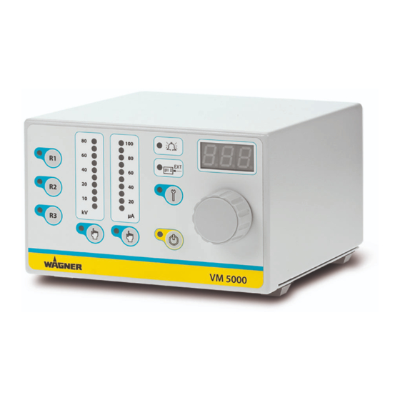
Page 18: Operating Elements And Connections
VM 5000 EDITION 07/2014 ORDER NUMBER DOC 2344501 OPERATING MANUAL OPERATING ELEMENTS AND CONNECTIONS 5.5.1 OPERATING ELEMENTS FRONT SIDE 1 Push button "Recipe 1" 2 Push button "Recipe 2" 3 Push button "Recipe 3" 4 Illuminated display "R1" Lights up if recipe 1 is used. - Page 19 VM 5000 EDITION 07/2014 ORDER NUMBER DOC 2344501 OPERATING MANUAL μA VM 5000 B_03271 15 Display LED: 7 segments, three-digit number Displays set values and actual values for high-voltage and for the spray current Display showing error number in the event of warnings and malfunctions...
-
Page 20: Connections On The Rear Side
Warning - Do not disconnect under voltage. 27 Interface Warning - Do not disconnect under voltage. 28 Cover of the interface connection 29 Cover of the service connection Only for Wagner service personnel 30 Knurled nut grounding Grounding cable connection to the signal ground... -
Page 21: Commissioning And Operation
VM 5000 EDITION 07/2014 ORDER NUMBER DOC 2344501 OPERATING MANUAL COMMISSIONING AND OPERATION TRAINING ASSEMBLY/COMMISSIONING STAFF WARNING Incorrect installation/operation! Risk of injury and equipment damage. The commissioning staff must have the technical skills to safely undertake commissioning. When commissioning and for all work, read and follow the operating manual and safety regulations for the additionally required system components. -
Page 22: Additional Components
2 for the compressed air supply 4 Grounding cable to the signal ground The operation of the VM 5000 in combination with the high-voltage Universal cascade is described in detail in the operating manual of the high-voltage Universal cascade. WARNING Incorrect installation/operation! Risk of injury and equipment damage. -
Page 23: Placement Of The Device
VM 5000 EDITION 07/2014 ORDER NUMBER DOC 2344501 OPERATING MANUAL NOTICE Impurities in the spraying system! Spray gun blockage, products harden in the spraying system. Flush the spray gun and paint supply with a suitable cleaning agent. PLACEMENT OF THE DEVICE... -
Page 24: Grounding
VM 5000 EDITION 07/2014 ORDER NUMBER DOC 2344501 OPERATING MANUAL GROUNDING It is important for systems safety and to achieve an optimum coating, that all system components such as work pieces, conveyors, paint supply, control unit and booth or spraying stand are perfectly grounded. - Page 25 VM 5000 EDITION 07/2014 ORDER NUMBER DOC 2344501 OPERATING MANUAL Grounding scheme (example) Conveyor Note for the sprayer Control unit Safety shoes and gloves, if used, must be static dissipative. Grounding Work piece cable Product supply R max < 1 MΩ...
-
Page 26: Example: Aircoat Spraying System
11 Stop valve 18 Tank for return fl ow Trolley 12 Air pressure regulator 19 Paint tank Air pressure regulator + air fi lter 13 VM 5000 control unit 20 Tank, cleaning agent Product suction system 14 Protective hose 21 Mains cable... - Page 27 Lay grounding cable from the grounding screw on the device to the signal ground and ensure that all other conductive parts within the working area are grounded. Connect the VM 5000 electrostatic control unit via the mains cable to the socket interlocked with the extraction system.
-
Page 28: Device Configuration
Overview of the device confi guraton levels: There are 3 levels: Level 1: for operator Level 2: for Wagner Service Level 3: for Wagner production plant 6.8.1 PARAMETER OVERVIEW OF LEVEL 1 FOR USERS Parameter Value Description C11 External release The device functions as a standalone device. - Page 29 VM 5000 EDITION 07/2014 ORDER NUMBER DOC 2344501 OPERATING MANUAL C14 Operating mode Operation with GM 5000EA or GM 5000EAC manual spray gun This parameter (factory setting) is linked to Automatic electrostatic spray gun parameter C11. High voltage Universal 3 G cascade If parameter High voltage Universal 7.5 G cascade...
-
Page 30: Access To The Device Configuration Mode
VM 5000 EDITION 07/2014 ORDER NUMBER DOC 2344501 OPERATING MANUAL 6.8.2 ACCESS TO THE DEVICE CONFIGURATION MODE Procedure: 1. Switch to "Standby" by pressing the "Standby" button (17). The orange LED "Standby" (18) μA lights up. VM 5000 B_03682 2. Press and hold the "Service"... -
Page 31: Setting Example "Parameter C11
For ease of operation the confi guration settings are divided into three groups. The fi rst group is for the end user, the other two groups are password protected and reserved for Wagner Service and the Wagner production sites or the Wagner Service Center, which have the necessary infrastructure. - Page 32 VM 5000 EDITION 07/2014 ORDER NUMBER DOC 2344501 OPERATING MANUAL μA VM 5000 B_03682 21 20 The fl ashing LED display (13) indicates that the parameter value "oFF" in the display (15) can be changed with the universal control dial (16). Possible values in C11 are "on" or "oFF".
-
Page 33: Operating Hours Counter / Service Display
VM 5000 EDITION 07/2014 ORDER NUMBER DOC 2344501 OPERATING MANUAL OPERATING HOURS COUNTER / SERVICE DISPLAY Two hour counters are integrated into the control unit. The absolute counter measures the spray gun's current operating hours and with the maintenance hours counter, the spray gun's maintenance intervals can be determined and monitored. -
Page 34: Maintenance Counter Set Up And Reading
VM 5000 EDITION 07/2014 ORDER NUMBER DOC 2344501 OPERATING MANUAL 6.9.1 MAINTENANCE COUNTER SET UP AND READING When using the device for the fi rst time, the function for the maintenance hours counter is deactivated. This function can be activated with the "R3" push button (3). The maintenance interval limit can be set within a range of 0 to 999 hours. -
Page 35: External Interface
VM 5000 EDITION 07/2014 ORDER NUMBER DOC 2344501 OPERATING MANUAL 6.10 EXTERNAL INTERFACE The control unit is equipped with an interface. Before using it, you have to select the respective parameters in the device confi guration. J. WAGNER AG Industriestrasse 22 CH - 9450 Altstätten... - Page 36 VM 5000 EDITION 07/2014 ORDER NUMBER DOC 2344501 OPERATING MANUAL Pin no. Designation Description External release Potential-free contact between pin 1 and pin 8 (ground) - Closed Release issued - Open Release not issued Fault reset Potential-free contact (button) between pin 2 and pin 8 (ground) - If there is a fault, it can be acknowledged by pressing a button.
-
Page 37: Operation
VM 5000 EDITION 07/2014 ORDER NUMBER DOC 2344501 OPERATING MANUAL OPERATION Observe safety instructions in Chapter 4. TRAINING THE OPERATING STAFF WARNING Incorrect operation! Risk of injury and equipment damage. The operating staff must be qualifi ed to operate the entire system. -
Page 38: Control Unit Start Up
VM 5000 EDITION 07/2014 ORDER NUMBER DOC 2344501 OPERATING MANUAL DANGER High-voltage fi eld! Danger to life from malfunction of heart pacemakers. Make sure that persons with pace makers: Do not work with the electrostatic spray gun. Stay outside the area of the electrostatic spray gun/work piece. -
Page 39: Setting And Saving Recipes
VM 5000 EDITION 07/2014 ORDER NUMBER DOC 2344501 OPERATING MANUAL 4. The control unit is ready for operation. Note: Each starting sequence is concluded μA by allocating the saved set data in recipe "R1". VM 5000 B_03682 SETTING AND SAVING RECIPES Set values for the high-voltage (kV) and for the spray current limiting (μA) are stored in... -
Page 40: Setting The High-Voltage
VM 5000 EDITION 07/2014 ORDER NUMBER DOC 2344501 OPERATING MANUAL 7.4.1 SETTING THE HIGH-VOLTAGE Procedure: 1. Press the "High-voltage" button (21) to adjust the high-voltage. The LED (22) indicates that high-voltage μA is selected. VM 5000 B_03682 22 21 2. The high-voltage can now be adjusted... -
Page 41: Setting The Current Limiting
VM 5000 EDITION 07/2014 ORDER NUMBER DOC 2344501 OPERATING MANUAL 7.4.2 SETTING THE CURRENT LIMITING Procedure: 1. Press the "Current limiting" button (19) to adjust the limitation of the spray current. μA The LED (20) indicates that current limiting is selected. -
Page 42: Display During Spraying
VM 5000 EDITION 07/2014 ORDER NUMBER DOC 2344501 OPERATING MANUAL 7.4.3 DISPLAY DURING SPRAYING Ready to spray using R2 recipe. See fi gure below. Control unit in ready position. The LEDs for the set values light up in a dot arrangement and the value for high-voltage is displayed in digits. -
Page 43: Standby Mode
VM 5000 EDITION 07/2014 ORDER NUMBER DOC 2344501 OPERATING MANUAL STANDBY MODE If you want to spray without high-voltage, select the standby mode. Press push button (17) briefl y and the "Standby" LED display (18) lights up. All the other LEDs go out. -
Page 44: Display "Conduct Service
VM 5000 EDITION 07/2014 ORDER NUMBER DOC 2344501 OPERATING MANUAL DISPLAY "CONDUCT SERVICE" μA VM 5000 B_03682 Prerequisite: The function "Maintenance interval limit" is activated. "Conduct service on spray gun" Once the time for the defi ned maintenance interval has expired, the LED display (13) starts to fl ash. -
Page 45: Troubleshooting And Rectification
VM 5000 EDITION 07/2014 ORDER NUMBER DOC 2344501 OPERATING MANUAL TROUBLESHOOTING AND RECTIFICATION Functional fault Cause Remedy No illuminated display lights up Mains supply not switched on Check and switch on mains supply Fuses defective Replace fuses Wagner Service No high-voltage... - Page 46 Coil current too big Cascade of the connected gun is Check/replace gun defective E21-E29 Exception error Hardware defect has occurred If problem persists, contact Wagner Service Team Cabinet door In Aquacoat operation: switching Close Aquacoat cabinet door monitoring on the high-voltage with an open...
-
Page 47: Maintenance And Repair
DIN EN 60079-15:2011 have to be fulfi lled. This inspection may only be carried out by an authorized person or by trained Wagner Service Personnel. When carrying out the leakage tightness test, the mains input terminal serves as a test port. -
Page 48: Accessories
264626 Mains cable USA 2 m; 6.6 ft 264625 Mains cable Japan 3 m; 9.8 ft 2317600 Interface cable VM 5000, 10 m; 32.8 ft 130215 Grounding cable, 10 m, 32.8 ft 264332 Grounding cable, complete 0.75 m; 2.5 ft... -
Page 49: Spare Parts
Risk of injury and equipment damage. Have repairs and part replacements be carried out only by specially trained staff or a WAGNER service center. Before all work on the device and in the event of work interruptions: - Switch off the energy/compressed air supply. -
Page 50: Spare Parts List Vm 5000
VM 5000 EDITION 07/2014 ORDER NUMBER DOC 2344501 OPERATING MANUAL 12.2 SPARE PARTS LIST VM 5000 B_04168... - Page 51 9922017 Serrated lock washer, externally toothed 9903311 Recessed head raised fi llister head screw, H form 241323 Cover, white 2350436 Print VM 5000 FM rear panel, complete (ET) 263400 Distance bush 9922011 Serrated lock washer, externally toothed 9910103 Hexagon nut...
-
Page 52: Warranty
The manufacturer will not be held liable or will only be held partially liable if third-party accessories or spare parts have been used. With genuine WAGNER accessories and spare parts, you have the guarantee that all safety regulations are complied with. - Page 53 VM 5000 EDITION 07/2014 ORDER NUMBER DOC 2344501 OPERATING MANUAL...
- Page 54 VM 5000 EDITION 07/2014 ORDER NUMBER DOC 2344501 OPERATING MANUAL...
- Page 55 VM 5000 EDITION 07/2014 ORDER NUMBER DOC 2344501 OPERATING MANUAL...
- Page 56 Order No. 2344501 Edition 07/2014 Germany Phone E-mail Switzerland Phone More contact adresses on the Internet at: Enterprises/Sites/WAGNER worldwide Subject to changes without notice...
Need help?
Do you have a question about the VM 5000 and is the answer not in the manual?
Questions and answers