Table of Contents
Advertisement
Quick Links
User Manual
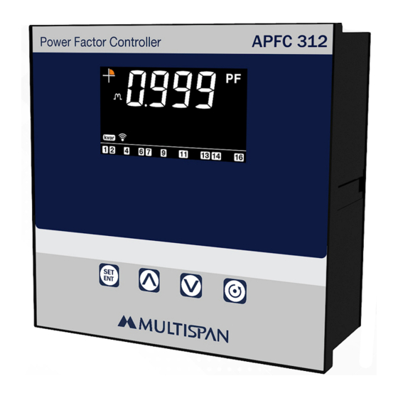
APFC 312
Multispan Control Instruments Pvt Ltd
72/B, Phase 1, GIDC Estate, Vatva, Ahmedabad-382445, Gujarat, India.
service@multispanindia.com
www.multispanindia.com
+91-9978991482
Technical Specification
INPUT:
Voltage AC
Input voltage AC
20 to 300V AC (L - N)
35 to 520V AC (L - L)
Burden
< 7 VA
Frequency
50/60 Hz
Current AC(3 CT Sensing)
Primary CT Ratio
5 to 9999 Amp Selectable
Secondary Current Ac
0.01 To 5.0 Amp (Without CT)
Burden
< 0.4 VA
Up to 6A Continuous
Overload
DISPLAY, KEY & LED:
Upper: 4 Digit,7 seg,0.60"
Display
Lower: 7 Digit,7 seg,0.38"
Key
SET/ENT, INC, DEC, EXIT
DIMENSION:
144 (H) x 144 (W) x 70 (D) mm
Size
137 (H) x 137 (W) mm
Panel Cutout
CONTROLLING RANGE:
Operating Mode
Kvar / Intel / Manual
Programmable
0 to 25 KVAr
Hysteresis
OUTPUT SPECIFICATION:
12 Stage Capacitor Relay
Relay Type
(NO-C)
Rating
7A, 250V AC
AUXILIARY SUPPLY:
Supply voltage
100V To 270V AC (L-N)
Power consumption
Approximately 7VA
(VA RATING)
ACCURACY:
Class 1.0 (Standard)
ENVIRONMENT CONDITION:
Operating Temp.
0°C to 55°C
UP to 95% RH
Relative Humidity
(non-condensing)
Page 2
Advertisement
Table of Contents

Related Manuals for MULTISPAN APFC 312


Summary of Contents for MULTISPAN APFC 312
- Page 1 100V To 270V AC (L-N) Power consumption Approximately 7VA (VA RATING) ACCURACY: Class 1.0 (Standard) Multispan Control Instruments Pvt Ltd ENVIRONMENT CONDITION: Operating Temp. 0°C to 55°C 72/B, Phase 1, GIDC Estate, Vatva, Ahmedabad-382445, Gujarat, India. UP to 95% RH...
-
Page 2: Terminal Connection
Panel Cutout Outline Dimension (mm) Dimension (mm) 30 29 28 27 26 25 24 23 22 21 20 19 18 34 33 32 APFC 96-L6 APFC 312 Alarm Capacitor Bank Key Operation APFC 312-A2-00 PARAMETER SETTING MODE www.multispanindia.com To Set Parameter Value... -
Page 3: Display Pages
Press Display Pages Actual P.F KW L2 kvar 1 2 3 kvar 1 2 3 4 Press Press key to 5 sec Require Kvar KW L3 kvar 1 2 3 kvar 1 2 3 Press Press Capacitor Bank Current Kvar L1 kvar kvar 1 2 3... -
Page 4: Factory Reset
Press Press Kva L3 kvar kvar Press (Enter Capacitor Bank Kvar) Only If MANUAL Press Is Selected (Capacitor Bank 1 to 12) Line Current 1 kvar kvar Press Press key to save & exit Line Current 2 Factory Reset kvar Press Actual P.F kvar... -
Page 5: Parameter Range
Parameters ( 0001 to 9999 sec ) kvar (Scan Time) Actual P.F 1 2 3 Press kvar (10 - 500mA) Press key to 5 sec (Min. Operating Current ) kvar Enter Password Press key to save & exit As Per set in configuration kvar Press ( 5 to 9999) - Page 6 Working Controlling Page Control Mode: 1) Kvar Mode : Actual P.F Ÿ When this mode is selected, capacitor bank switching step is not fixed and the program automatically selct the most appropriate steps to switch kvar capacitor bank “ON’ or “OFF” in order to achieve target PF by shortest reaction time with minimum number of steps.
-
Page 7: Other Setting
Other Setting : Four Quadrant Representation Ÿ As Per IEC 387 IF Reactive Power is Positive (+Ve) than it is consider as a 1) SCAN TIME : Inductive Load if Reactive Power is Negative (-Ve) then it is consider as Ÿ... -
Page 8: Safety Precaution
Installation Guidelines Mechanical Installation Guideline 1) Do not allow pieces of metal, wire clippings, or fine metallic fillings from installation 1) Prepare the panel cutout with proper dimensions as shown above. to enter the product or else it may lead to a safety hazard that may in turn endanger 2) Fit the unit into the panel with the help of clamp given.
Need help?
Do you have a question about the APFC 312 and is the answer not in the manual?
Questions and answers