
Subscribe to Our Youtube Channel
Related Manuals for Parker KE-MT Series


Summary of Contents for Parker KE-MT Series
- Page 1 Adsorption dryer KE-MT 120–600 Operating manual 14/02/2022 rev07 EN Cod: 398H271932...
-
Page 3: Table Of Contents
EN | User Manual Index Machine passport General information Manufacturer’s details ......................4 Details on the dryer ........................4 About these operating instructions ................... 5 For your own safety General safety notes ......................... 6 Intended use of the dryer ......................7 Safety notes on specifi c operating phases ................ - Page 4 EN | User Manual Summary of faults ........................42 Annex with technical documentation Technical data ......................... 47 Replacement and wear part list ....................48 Logic control diagram ......................50 Flow diagram .......................... 52 Dimensional drawing ......................53 KE-MT 120-600...
-
Page 5: Machine Passport
EN | User Manual Machine passport Machine passport Type designation Order no. Order ID. Build no. Vessel no. Vessel no. Year of manufacture It is the responsibility of the owner, ◊ to enter for the fi rst time any appliance data not stated above, ◊... -
Page 6: General Information
General information Manufacturer’s details Name and address Parker Hannifi n Manufacturing S.r.l. Sede Legale: Via Sebastiano Caboto 1, Palazzina “A” 20094 Corsico (MI) Italy Sede Operativa: Gas Separation and Filtration Division EMEA - Strada Zona Industriale, 4 35020 S.Angelo di Piove (PD) Italy tel +39 049 971 2111- fax +39 049 9701911 Web-site: www. -
Page 7: About These Operating Instructions
EN | User Manual General information About these operating instructions These operating instructions contain basic information on the safe use of the dryer. Characters and symbols used Work steps that you have to carry out in the sequence stated are marked by black tri- angles. -
Page 8: For Your Own Safety
EN | User Manual For your own safety For your own safety The dryer has been built in accordance with the state of the art and the recognized technical safety regulations. Nevertheless, there is a risk of personal injury and damage to property when the dryer is used, if ◊... -
Page 9: Intended Use Of The Dryer
EN | User Manual For your own safety skidding! Disassembly and disposal ◊ Dispose all parts of the dryer, the drying agent, and all other operating materials in an envi- ronmentally safe way and in accordance with all current statutory regulations. Equipment containing electrical components must be disposed separately col- lected with electrical and electronic waste according to local and currently leg- islation. - Page 10 EN | User Manual For your own safety Maintenance of the dryer and fault removal ◊ Carry out maintenance work only when the plant has been shut down and depressurised! ◊ The factory settings on the control board in the switchbox must not be changed on any account without prior approval by the manufacturer.
-
Page 11: Signs, Instruction Plates And Danger Zones At The Dryer
EN | User Manual For your own safety Signs, instruction plates and danger zones at the dryer Signs and instructions Vessel plate Vessel plate Type plate of the dryer Please note the above plates and instructions attached to the dryer. Ensure that they are not removed and are always readable. - Page 12 EN | User Manual For your own safety Hazard areas on the dryer Hazard caused by electrical voltage Hazard caused by overpressure Hazard caused by sudden air ejection during expansion Symbol Hazard area Warning against hazardous electrical voltage Different parts of the dryer carry electrical current. These parts may be connected, opened, and maintained by authorized specialist personnel only.
-
Page 13: Transportation, Installation And Storage
EN | User Manual Transportation, installation and storage Transportation, installation and storage Danger due to incorrect transportation! The dryer must be transported by authorized and qualifi ed specialist personnel only. During transportation all applicable national regulations for accident pre- vention must be complied with. Otherwise there is a risk of personal injury. Always adhere to the stickers and notes on the packaging of the dryer! ◊... - Page 14 EN | User Manual Transportation, installation and storage ◊ The dryer should be installed with suffi cient spacing at the top, sides, and rear, in order to be able to carry out maintenance work and change the drying agent without any hindranc- es (see fi gure).
-
Page 15: Anchoring The Dryer
EN | User Manual Transportation, installation and storage Transport by crane Transport the dryer in an upright position to its location of installation. For this purpose, attach a girder with suit- able fi xtures to ensure that the dryer is lifted at the centre and that the upper pipe bridge is not crushed between the vessels (see fi gure). -
Page 16: Storing The Dryer
EN | User Manual Transportation, installation and storage Storing the dryer If the dryer is to be stored for an extended period of time, the storage location must meet the following conditions: ◊ The dryer must not be stored in the open air. ◊... -
Page 17: Technical Product Description
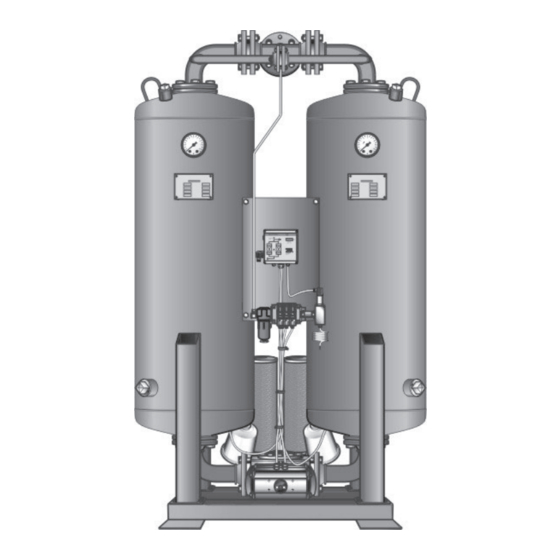
EN | User Manual Technical product description Technical product description Summary Drawing Regeneration gas orifi ce Filling point Pressure gauge (PI) (Option: Safety valve connection) Vessel On/Off-Switch Power supply Control box Filter for control gas Solenoid valve block (Y1-Y4) Drain point Front view Check valve V3 Check valve V2... -
Page 18: Function Description
EN | User Manual Technical product description Function description The dryer dries the compressed air supplied by the compressor and makes it available for industrial use. If so, installed up- and downstream fi lters purify the compressed air, feeded to resp. dissipat- ed from the dryer. - Page 19 EN | User Manual Technical product description Expansion phase During the expansion phase the pressure in the right chamber is released via the muffl er down to ambient pressure within just a few seconds. The outfl ow of the compressed air becomes noticeable due to a sudden powerful fl ow noise at the muffl er.
-
Page 20: Available Options
EN | User Manual Technical product description Available options The following options are available for the dryer: ◊ Start-up device ◊ Outside installation ◊ Auxiliary heater ◊ Bypass line ◊ Signalling contacts of control system ◊ Compressor synchronisation ◊ Dewpoint-sensing control ◊... - Page 21 EN | User Manual Technical product description transmission of operating signals and for the output of dewpoint alarms. Compressor synchronisation Compressor synchronisation helps reduce energy costs, as the dryer can be operated inde- pendently of the compressor. When the compressor is switched off, the regeneration gas return ensures that regenera- tion is continued, as soon as a certain compressed air volume is reached behind the dryer.
- Page 22 EN | User Manual Technical product description Pneumatic control Condensate drain systems are installed to drain water that has collected in the preliminary or afterfi lter from the fi lter. There are two distinct types of condensate drain system, namely level-controlled systems and time-controlled systems.
-
Page 23: Installation
EN | User Manual Installation Installation Only authorized and qualifi ed specialist personnel may carry out work on pipes and electrical systems. As soon as the dryer has been set up at its installation location, you can install the com- pressed air infeed and outlet lines make the electrical connections. -
Page 24: Connect Piping
EN | User Manual Installation Connect piping In order to ensure that the dryer operates optimally, the dryer must be assembled into the compressed air system free of all stresses. Ensure before connection that all infeed and outfeed compressed air lines and valves are clean and undamaged. -
Page 25: Installing The Electrical Connection
EN | User Manual Installation Installing the electrical connection Warning against electrical voltage Only qualifi ed specialist personnel may carry out work on the electrical system! Installing the supply cable The components of the dryer have been connected to the control cabinet at the factory. You only need to connect the control cabinet to the electrical supply cable. - Page 26 EN | User Manual Installation Connecting the external signalling lines For compressor synchronisation The controller is fi tted as standard with a digital input which makes the dryer regeneration dependent on operation of the compressor (switch S1 on the controller’s circuit board, see also fi gure below).
-
Page 27: Start-Up
EN | User Manual Start-up Start-up Warning! The dryer must be taken into operation by trained personnel only! Untrained personnel does not have the required knowledge. Such personnel might cause serious faults. Note: You can order the initial commissioning and start-up from the manufacturer and have your personnel trained by the manufacturer. -
Page 28: Setting Times Of The Operating Phases
EN | User Manual Start-up Setting times of the operating phases In its standard version the dryer is delivered with a time-dependent control system. The phase sequence occurs in a fi xed cycle. With the optional dewpoint-sensing control, the dryer can also be operated at variable cycles (depending on the dewpoint). - Page 29 EN | User Manual Start-up Display panel The display panel at the switchbox is equipped with LEDs (light emitting diodes) and a digital display, indicating the operating status of the dryer: Display panel at the switchbox LED Power (1) LED is on when dryer is switched on. Flow diagram (2) The current operating phases of the dryer are indicated by means of 4 LEDs: Vessel B2...
- Page 30 EN | User Manual Start-up Display Explanation Default display: The fi gure to the left indicates the current processing step; the fi gure to the right shows the remaining time in seconds. In this example, step 2 is being completed, whereby there are 215 seconds remaining.
-
Page 31: Start Up Dryer
EN | User Manual Start-up Start up dryer Warning against sudden air ejection! During expansion the pressure is released suddenly through the muffl er: ◊ A loud cracking noise occurs which can injure your hearing. ◊ Particles carried in the air fl ow act like bullets and can injure your eyes or skin. - Page 32 EN | User Manual Start-up Operating the dryer for the fi rst time (or after a change of drying agent) separately Depending on the transportation and storage conditions, the drying agent in the chambers can already be loaded with humidity from the environment. At each fi rst start-up it makes sense therefore to operate the dryer from some time separately from the compressed air system.
-
Page 33: Changing Cycle Mode (Optional)
EN | User Manual Start-up Changing cycle mode (optional) When can I change cycle mode? If the dryer has been successfully commissioned and is equipped with one of the following options: ◊ compressor synchronisation or ◊ dewpoint-sensing control it can be set to economy cycle mode. When should I change cycle mode? Cycle changes should be made during the pressure build-up phase and prior to switchover;... -
Page 34: Monitoring Dryer Operation
EN | User Manual Monitoring dryer operation Monitoring dryer operation The dryer operates fully automatically. However, you should carry out the regular checks described in the Chapter Maintenance and repair of the dryer. Warning against sudden air ejection! During expansion the pressure is released suddenly through the muffl er: ◊... -
Page 35: Shutdown And Restart Dryer
EN | User Manual Shutdown and restart dryer Shutdown and restart dryer In the following cases, the dryer must be fully shut down and depressurised: ◊ In the event of an emergency or malfunction ◊ For maintenance work ◊ For dismantling Risk of injury from escaping compressed air! Never remove any parts of the dryer, or manipulate the same in any way, as long as the unit is pressurised! Suddenly escaping compressed air might cause... -
Page 36: If Work Is To Be Carried Out On The Electrical System
EN | User Manual Shutdown and restart dryer If work is to be carried out on the electrical system Depressurise and shut down the dryer, following the instructions in the above chapter. Risk of injury due to voltage-carrying parts! The electrical supply cable and external power lines are live even after the dryer is switched off and, in the event of body contact, may cause serious injury! Before carrying out any work on the electrical system, the electrical supply cable and all external power lines must be made voltage-free! -
Page 37: Maintenance And Repair Of The Dryer
EN | User Manual Maintenance and repair of the dryer Maintenance and repair of the dryer In order to allow maintenance work on the dryer to be carried out effi ciently and without dan- ger for maintenance personnel, you should comply with the following instructions. Notes on maintenance Danger! There is a very considerable risk of personal injury, when carrying out work on... -
Page 38: Regular Maintenance Intervals
EN | User Manual Maintenance and repair of the dryer Regular maintenance intervals Note: If a chamber has been depressurised, e.g. after completion of the ex-pansion phase, and the pressure remains above 0 bar, the chamber is pressurised by what is known as ram pressure. This might be due to ◊... -
Page 39: Instructions For Use Of The Dongle
EN | User Manual Maintenance and repair of the dryer When carrying out any maintenance work, comply with the following safety instructions: Danger! There is a very considerable risk of personal injury, when carrying out work on the activated and pressurised dryer. Danger! Before commencing any maintenance tasks always shut down the dryer as described on page... -
Page 40: Daily Maintenance Tasks
EN | User Manual Maintenance and repair of the dryer Daily maintenance tasks Carry out visual and function check on the complete dryer Check dryer for external damage or unusual noise generation. Duly eliminate any defects found. If message SEr. is displayed, a routine service must be completed: Contact the service department of the manufacturer. - Page 41 EN | User Manual Maintenance and repair of the dryer Renew muffl ers The dryer is equipped with a muffl er. If the muffl er becomes blocked, a dam pressure is gen- erated which in extreme cases may cause the muffl er to burst. Hazard caused by blocked muffl...
- Page 42 EN | User Manual Maintenance and repair of the dryer Warning! The dew point sensor is a sensitive measuring device. It can be damaged if subjected to forceful vibrations or shocks. Therefore, please handle the dew point sensor with great care at all times. In order to limit the impact on the dryer operation to a minimum, we recommend that you contact the manufacturer well in advance and order a new dewpoint sensor.
-
Page 43: Notes On Further Maintenance Work
EN | User Manual Maintenance and repair of the dryer Notes on further maintenance work Every 12 months Replacing pilot valves The pilot valves are part of every service kit and must be replaced every 12 months. Every 48 months In accordance with national regulations, a pressure vessel inspection may be prescribed to be carried out at regular intervals by an independent supervisory offi ce. -
Page 44: Identify And Eliminate Faults
EN | User Manual Identify and eliminate faults Identify and eliminate faults The following table provides information on what designatory abbreviations are to be used for the various components. These designations are also found in the technical documentation. Used abbreviation Component Pressure gauge V1 (Y2–Y1) - Page 45 EN | User Manual Identify and eliminate faults Fault Possible cause Remedy Excessive compressed Leakage Check condensate trap at • • air consumption the upstream fi lter (option); clean, if necessary. Dryer does not switch Solenoid valve Y1/Y2 does Check supply voltage, ca- •...
- Page 46 EN | User Manual Identify and eliminate faults Fault Possible cause Remedy Pressure dew point is Compressed air inlet tem- Reduce compressed air inlet • • not reached perature is too high. temperature or pre-connect a compressed air cooler. Control board is defective. Check control board, if nec.
- Page 47 EN | User Manual Identify and eliminate faults With dewpoint-sensing control (optional) Fault code Description of Possible cause Remedy fault Upper measuring Drying capacity See instructions for range limit exceeded exceeded. commissioning. If the • drying agent is wet, replace it. Error in programme.
-
Page 48: Annex With Technical Documentation
EN | User Manual Annex with technical documentation Annex with technical documentation This annex comprises the following information and technical documentation: ◊ Technical data ◊ Replacement and wear parts list ◊ Logic control diagram ◊ Flow diagram ◊ Dimensional drawing KE-MT 120-600... -
Page 49: Technical Data
EN | User Manual Annex with technical documentation Technical data Operating Range Type KE-MT 120–600 Fluid group Max. operating pressure 10 bar Min. operating pressure 6 bar min. ambient temperature ≥+1°C (33,8°F) max. ambient temperature ≤+50°C (122°F) Noise level : +3 dB (A) relative to free fi eld measurement, 1 m 105 –... -
Page 50: Replacement And Wear Part List
EN | User Manual Annex with technical documentation Replacement and wear part list Note: When exchange or replacement parts are ordered, always state the dryer type and the build no. of the dryer. These data are found on the type plate. Service-kits* For model Maintenance... - Page 51 EN | User Manual Annex with technical documentation Desiccant packs ** Type Order-ID. KE-MT 120 KEN2000DESMIX KE-MT 150 KEN2600DESMIX KE-MT 200 KEN3100DESMIX KE-MT 250 KEN3800DESMIX KE-MT 300 KEN5000DESMIX KE-MT 380 KEN6000DESMIX KE-MT 500 KEN8000DESMIX KE-MT 600 KEN10000DESMIX ** including dust sieve and seals KE-MT 120-600...
-
Page 52: Logic Control Diagram
EN | User Manual Annex with technical documentation Logic control diagram Adsorption in B1 and regeneration in B2 KE-MT 120-600... - Page 53 EN | User Manual Annex with technical documentation Regeneration in B1 and adsorption in B2 KE-MT 120-600...
-
Page 54: Flow Diagram
EN | User Manual Annex with technical documentation Flow diagram Pos. Designation Pos. Designation Dust sieve Muffl er Stop valve for pressure gauge Control system Pressure gauge PI Control air fi lter Main inlet valve V1 Solenoid valve block Y1–Y4 Check valve V2/V3 Options: Regeneration gas orifi ce plate... -
Page 55: Dimensional Drawing
EN | User Manual Annex with technical documentation Dimensional drawing KE-MT 120 & KE-MT 600 Dimensions [mm] Connection Weight [kg] Type Inlet Outlet KE-MT 120 DN 50 DN 50 1060 2080 KE-MT 150 DN 65 DN 65 1270 2120 KE-MT 200 DN 65 DN 65 1350... - Page 56 A division of Parker Hannifi n Corporation Parker Hannifi n Manufacturing S.r.l. Sede Legale: Via Sebastiano Caboto 1, Palazzina “A” 20094 Corsico (MI) Italy Sede Operativa: Gas Separation and Filtration Division EMEA - Strada Zona Industriale, 4 35020 S.Angelo di Piove (PD) Italy tel +39 049 971 2111- fax +39 049 9701911 Web-site: www.
Need help?
Do you have a question about the KE-MT Series and is the answer not in the manual?
Questions and answers