
Subscribe to Our Youtube Channel
Related Manuals for Parker KE-MT 120


Summary of Contents for Parker KE-MT 120
- Page 1 Adsorption dryer KE-MT 120–600 Operating manual 14/02/2022 rev07 EN Cod: 398H271932...
-
Page 3: Table Of Contents
Regular maintenance intervals ....................36 Instructions for use of the dongle ................... 37 Daily maintenance tasks ......................38 Maintenance work to be completed every 12 months ............38 Notes on further maintenance work ..................41 Identify and eliminate faults KE-MT 120-600... - Page 4 EN | User Manual Summary of faults ........................42 Annex with technical documentation Technical data ......................... 47 Replacement and wear part list ....................48 Logic control diagram ......................50 Flow diagram .......................... 52 Dimensional drawing ......................53 KE-MT 120-600...
-
Page 5: Machine Passport
Further important data on the dryer such as the details on the permissible operating pressure and the electrical connection are found on the type plate (for position of the type plate see page 9 ) KE-MT 120-600... -
Page 6: General Information
General information Manufacturer’s details Name and address Parker Hannifi n Manufacturing S.r.l. Sede Legale: Via Sebastiano Caboto 1, Palazzina “A” 20094 Corsico (MI) Italy Sede Operativa: Gas Separation and Filtration Division EMEA - Strada Zona Industriale, 4 35020 S.Angelo di Piove (PD) Italy tel +39 049 971 2111- fax +39 049 9701911 Web-site: www. -
Page 7: About These Operating Instructions
These operating instructions must be continuously available at the site where the dryer is used. We recommend to prepare a copy and to keep the same in a safe and freely accessible place next to the dryer. Keep the original document in a safe place. KE-MT 120-600... -
Page 8: For Your Own Safety
Please comply with the following instructions: ◊ When fi lling drying agents, wear a dust mask and eye protection! ◊ If a spillage occurs, any spilt drying agent must be taken up immediately. There is a risk of KE-MT 120-600... -
Page 9: Intended Use Of The Dryer
◊ Carry out maintenance work only when the plant has been shut down and depressurised! ◊ The factory settings on the control board in the switchbox must not be changed on any account without prior approval by the manufacturer. KE-MT 120-600... - Page 10 ◊ Dispose all parts of the dryer, the drying agent, and all other operating materials in an environmentally safe way and in accordance with all current statutory regulations. The waste code numbers of the drying agents can be obtained from the manufacturer (for the manufac- turer’s address see page “General information” a pagina 4). KE-MT 120-600...
-
Page 11: Signs, Instruction Plates And Danger Zones At The Dryer
Signs, instruction plates and danger zones at the dryer Signs and instructions Vessel plate Vessel plate Type plate of the dryer Please note the above plates and instructions attached to the dryer. Ensure that they are not removed and are always readable. KE-MT 120-600... - Page 12 At the universal shaft and the drives, there is a risk of injury from crushing during the switching from absorption to regeneration. Skid risk When emptying and fi lling the vessels with drying agent, there is a risk of skidding caused by spilt drying agent. KE-MT 120-600...
-
Page 13: Transportation, Installation And Storage
◊ The installation area must be level, fi rm and vibration-proof. It must have the necessary car- rying capacity for the weight of the dryer. The weight of the dryer is specifi ed in the technical data section of the annex. KE-MT 120-600... - Page 14 Therefore, adhere to the transport instructions outlined as follows. KE-MT 120-600...
-
Page 15: Anchoring The Dryer
Use suitable attachment material to anchor the dryer to the fl oor (see fi gure). In the case of vibrating fl oors: place the dryer on suitable vibration dampers Bores at the foot of the dryer KE-MT 120-600... -
Page 16: Storing The Dryer
If you wish to take the dryer back into service after an extended period of sto- rage, please proceed as described for its fi rst commissioning and start-up (see page 29). Store drying agents Do not store drying agents in the open air. Protect drying agents against humidity. KE-MT 120-600... -
Page 17: Technical Product Description
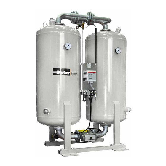
Filter for control gas Solenoid valve block (Y1-Y4) Drain point Front view Check valve V3 Check valve V2 Compressed air outlet Eyebolt Compressed air inlet Expansion valve V4 Expansion valve V5 Muffl er Main inlet valve V1 Rear view KE-MT 120-600... -
Page 18: Function Description
At the same time the other chamber is prepared for a renewed take-up of humidity. This process is called regeneration. The regeneration is subdivided into three phases: expansion, dehumidifi cation, and pres- sure build-up. With the dewpoint-sensing control option, the regeneration phase is followed by a standby phase. KE-MT 120-600... - Page 19 When the drying agent in the adsorbing chamber has taken up a suffi cient level of humidity, then the switchover between the vessels will be effected between the vessels. Following switchover, the above-described process is repeated, with the adsorption and regeneration now taking place in the respective different vessel. KE-MT 120-600...
-
Page 20: Available Options
The control system can also be equipped with an optional operation signalling contact with which the dryer operation can be monitored from an external device. Dryers with the optional dewpoint-sensing control are equipped with such a contact as standard. It is used for the KE-MT 120-600... - Page 21 Preliminary fi lters should be installed as close to the dryer as possible. The pipe feeding the air to the preliminary fi lter should be at a slight slope. It is recommended to install an afterfi lter behind the dryer to prevent contamination of the dried compressed air with desiccant particles. KE-MT 120-600...
- Page 22 Pneumatic control Condensate drain systems are installed to drain water that has collected in the preliminary or afterfi lter from the fi lter. There are two distinct types of condensate drain system, namely level-controlled systems and time-controlled systems. KE-MT 120-600...
-
Page 23: Installation
The data required to meet these preconditions are contained in the technical documentation attached in the annex. Warning! If the above preconditions are not complied with, a safe operation of the dryer cannot be assured. Also, the functionality of the dryer may be detrimentally affected. KE-MT 120-600... -
Page 24: Connect Piping
If you fi t a bypass line (8) with additional shutdown valve: Fit the line such that, when carrying out maintenance work on the dryer, the line system can continue to be supplied with compressed air. KE-MT 120-600... -
Page 25: Installing The Electrical Connection
Connect electrical cable to device the switchbox. adapter In all phases the dryer must be protected against short circuits by means of fuses. In order to relief cable strain, re-tighten the PG union. KE-MT 120-600... - Page 26 Connect the lines of the fault signalling system to relay K5 (see circuit diagram). Check bolt connections Before the initial start-up: Check all unions and bolt connections as well as the terminals in the control cabinet for secure seating; re-tighten if necessary. KE-MT 120-600...
-
Page 27: Start-Up
◊ owner-end and pressurised parts such as safety valves or other devices are not blocked up by dirt or paint, ◊ all compressed air system parts which are pressurised (valves, hoses etc.) are free from wear symptoms and defects. KE-MT 120-600... -
Page 28: Setting Times Of The Operating Phases
— with compressor synchronisation — in variable cycle mode (i.e. dew-point-cont- rolled). Position II is only relevant for operation with the optional compressor synchronisation and/ or dewpoint-sensing control Switchbox with ON/OFF switch KE-MT 120-600... - Page 29 Digital display (3) The digital display shows the individual programme steps and the respective remaining time. For details regarding the sequence of the individual processing steps and their duration, please refer to the logic control diagram, page 50. KE-MT 120-600...
- Page 30 This overpressure during regeneration is also designated as dam pressure. ◊ The dam pressure should not exceed 0.3 bar, otherwise read the instructions on page 38. ◊ During the pressure build-up phase the indication on the pressure gauge should again rise to operating overpressure level. KE-MT 120-600...
-
Page 31: Start Up Dryer
If the dryer is taken into operation for the fi rst time, or after a change of drying agent, the following intermediate step is meaningful. In the case of a restart situation, the following intermediate step can be skipped. KE-MT 120-600... - Page 32 (see also chapter , page 33). Then proceed as follows: Remedy fault: Look up possible cause of the fault, and how to remedy the same, in the table on page Remedy fault. Repeat the start-up procedure. KE-MT 120-600...
-
Page 33: Changing Cycle Mode (Optional)
How do I change cycle mode? Wait until the dryer has reached the pressure build-up phase (phase prior to switchover). One LED for Adsorption B1/B2 is on in the fl ow diagram. Set the ON/OFF switch to position The programme continues the cycle. KE-MT 120-600... -
Page 34: Monitoring Dryer Operation
Display Cause ◊ Upper measuring range limit exceeded ◊ Dewpoint sensor defective sens ◊ Dewpoint sensor not powered ◊ Cable defective -999 ◊ Sensor defective For instructions on how to eliminate faults, see chapter Identify and eliminate faults KE-MT 120-600... -
Page 35: Shutdown And Restart Dryer
During the expansion phase, the vessels are completely depressurised. Check the pressure in the dryer at both vessel pressure gauges. The pressure gauges should show value 0. Disconnect voltage supply Switch off the dryer by setting the ON/OFF switch to position 0. KE-MT 120-600... -
Page 36: If Work Is To Be Carried Out On The Electrical System
If disconnected, reconnect the voltage supply of the dryer. Pressurise and switch on the dryer as described in the section Open compressed air supply and switch on dryer on page 29. The dryer is now in operation again and operates fully automatically. KE-MT 120-600... -
Page 37: Maintenance And Repair Of The Dryer
◊ Never leave tools, loose parts or cloths at or on the dryer. ◊ Only use replacement parts that are suitable for the relevant function and meet the techni- cal requirements stipulated by the manufacturer. This is always the case, if you use original replacement parts only. KE-MT 120-600... -
Page 38: Regular Maintenance Intervals
Solenoid valve block Renew Dust sieves, gaskets, Renew drying agent* Upstream and down- Please see the enclosed operating instructions for the attached stream fi lter fi lters. Maintenance work has to be carried out as specifi ed in this document. KE-MT 120-600... -
Page 39: Instructions For Use Of The Dongle
Switch off the controller again and remove the dongle. Dispose of the unusable dongle and use a new one. KE-MT 120-600... -
Page 40: Daily Maintenance Tasks
The fi lter must therefore be inspected at least once every year. Depressurise the dryer and shut it down (see page 33 ). Unscrew muffl er as shown in the opposite fi gure. Replace muffl er and secure it. Restart dryer (see page 34). Open control air fi lter KE-MT 120-600... - Page 41 Renew dewpoint sensor To ensure precision dew point measurement, it is recommended to replace the dew point sensor every year. This period depends howev- er on the actual application and might thus be extended accordingly. Dewpoint sensor (1) KE-MT 120-600...
- Page 42 If no other maintenance work is to be carried out: Restart the dryer (see page 34 ). Place the protective caps (4, 5) onto the old dew point sensor and dispose of it in accor- dance with the applicable regulations. KE-MT 120-600...
-
Page 43: Notes On Further Maintenance Work
You should therefore replace dust fi lters along with the drying agent. Dust fi lters come with the “DESPAC” drying agent packs Replacing solenoids Solenoids come with the 48-month service kits. Replace them every 4 years. KE-MT 120-600... -
Page 44: Identify And Eliminate Faults
Remove any faults. Solenoid valve Y3/Y4 does Check supply voltage, ca- • • not close. ble, contacts and solenoid; replace, if necessary. Expansion valve V4/V5 does Check gaskets for contami- • • not close. nation, if nec. clean/renew. KE-MT 120-600... - Page 45 Pressure dew point is Operating pressure is too Increase operating pressure. • not reached low. Compressed air volume fl ow Reduce compressed air • is too high. volume fl ow KE-MT 120-600...
- Page 46 Check drying agent for • • contamination, if nec. renew drying agent. Regeneration gas too low. Check function of expansion valve V3/V4 and muffl er, if • • nec. renew muffl er or fi lter element. KE-MT 120-600...
- Page 47 The package includes a dongle with which you can reset the • • operating hours counter after maintenance has been carried out. For instructions on how to use the dongle see the enclosed information sheet (in the service kit). KE-MT 120-600...
-
Page 48: Annex With Technical Documentation
EN | User Manual Annex with technical documentation Annex with technical documentation This annex comprises the following information and technical documentation: ◊ Technical data ◊ Replacement and wear parts list ◊ Logic control diagram ◊ Flow diagram ◊ Dimensional drawing KE-MT 120-600... -
Page 49: Technical Data
EN | User Manual Annex with technical documentation Technical data Operating Range Type KE-MT 120–600 Fluid group Max. operating pressure 10 bar Min. operating pressure 6 bar min. ambient temperature ≥+1°C (33,8°F) max. ambient temperature ≤+50°C (122°F) Noise level : +3 dB (A) relative to free fi eld measurement, 1 m 105 –... -
Page 50: Replacement And Wear Part List
These data are found on the type plate. Service-kits* For model Maintenance Order-ID. Scope of delivery interval KE-MT 120 to Reset-module, control air fi lter ele- 12 / 36 months KE-MT12B KE-MT 600 ment, pilot valves, Reset-module, control air fi lter ele-... - Page 51 EN | User Manual Annex with technical documentation Desiccant packs ** Type Order-ID. KE-MT 120 KEN2000DESMIX KE-MT 150 KEN2600DESMIX KE-MT 200 KEN3100DESMIX KE-MT 250 KEN3800DESMIX KE-MT 300 KEN5000DESMIX KE-MT 380 KEN6000DESMIX KE-MT 500 KEN8000DESMIX KE-MT 600 KEN10000DESMIX ** including dust sieve and seals...
-
Page 52: Logic Control Diagram
EN | User Manual Annex with technical documentation Logic control diagram Adsorption in B1 and regeneration in B2 KE-MT 120-600... - Page 53 EN | User Manual Annex with technical documentation Regeneration in B1 and adsorption in B2 KE-MT 120-600...
-
Page 54: Flow Diagram
Stop valve for pressure gauge Control system Pressure gauge PI Control air fi lter Main inlet valve V1 Solenoid valve block Y1–Y4 Check valve V2/V3 Options: Regeneration gas orifi ce plate Dewpoint-sensing unit Expansion valve V4/V5 Start-up device Regeneration gas return line KE-MT 120-600... -
Page 55: Dimensional Drawing
EN | User Manual Annex with technical documentation Dimensional drawing KE-MT 120 & KE-MT 600 Dimensions [mm] Connection Weight [kg] Type Inlet Outlet KE-MT 120 DN 50 DN 50 1060 2080 KE-MT 150 DN 65 DN 65 1270 2120 KE-MT 200... - Page 57 A division of Parker Hannifi n Corporation Parker Hannifi n Manufacturing S.r.l. Sede Legale: Via Sebastiano Caboto 1, Palazzina “A” 20094 Corsico (MI) Italy Sede Operativa: Gas Separation and Filtration Division EMEA - Strada Zona Industriale, 4 35020 S.Angelo di Piove (PD) Italy tel +39 049 971 2111- fax +39 049 9701911 Web-site: www.
Need help?
Do you have a question about the KE-MT 120 and is the answer not in the manual?
Questions and answers