
Subscribe to Our Youtube Channel
Related Manuals for Parker TWP/TWB201


Summary of Contents for Parker TWP/TWB201
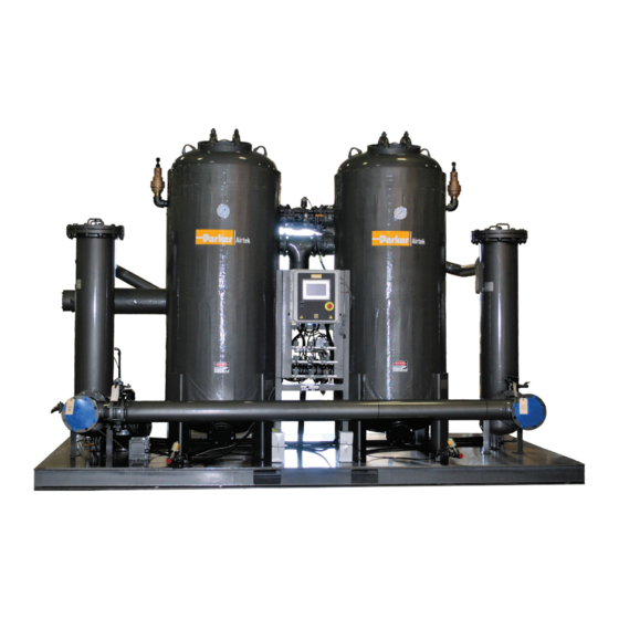
- Page 1 Externally Heated & Blower Purge Desiccant Dryers Models TWP/TWB201 – TWP/TWB7501 User Manual...
- Page 2 Please have the dryer serial number and model ready when contacting the factory. Factory Contact Information Phone 1-800-343-4048 For pricing, availability, and purchase orders: GSForders@parker.com For technical support and aftermarket: FAFparts@parker.com For product applications and technical sales: FAFquotes@parker.com...
-
Page 3: Table Of Contents
TWP/TWB201 – TWP/TWB7501 Contents Safety and Precautions Installation General Operation Flow Schematics Wiring Diagrams Start Up Timing Configuration Manual Stepping Controller Display & Operation Communications Shutdown Maintenance Spare Parts Lists Troubleshooting Technical Specifications... -
Page 4: Safety And Precautions
TWP/TWB201 – TWP/TWB7501 SAFETY AND PRECAUTIONS Use EXTREME CAUTION when working in the vicinity of the dryer. Adhere to all warning labels on dryer. Relieve pressure before servicing dryer or associated equipment. Disconnect power before servicing dryer. Always wear eye protection when in the vicinity of the dryer. Ear protection is recommended, especially if the dryer is being operated without mufflers. -
Page 5: Installation
TWP/TWB201 – TWP/TWB7501 INSTALLATION Inspect the dryer upon receipt for any damage that may have occurred during shipment. Each desiccant dryer is supplied with a User Manual, dryer general arrangement drawing, and ASME pressure vessel U1A data reports (where applicable). - Page 6 The following considerations must be taken when AND THE INFORMATION IT CONTAINS WILL NOT BE COPIED OR DISCLOSED TO OTHERS LANCASTER, NY OR USED FOR ANY PURPOSE OTHER THAN CONDUCTING BUSINESS WITH PARKER, AND SCALE UNITS 14086 USA WILL BE RETURNED AND ALL FURTHER USE DISCONTINUED UPON REQUEST BY PARKER.
- Page 7 TWP/TWB201 – TWP/TWB7501 Each elbow installed in the exhaust piping is equivalent to 10 feet of pipe. If the exhaust piping is vertical, a drip line must be installed to remove moisture. It is recommended to pipe the exhausts separately for ease of maintenance and troubleshooting.
-
Page 8: General Operation
TWP/TWB201 – TWP/TWB7501 GENERAL OPERATION The externally heated and blower purge desiccant dryers are designed to remove moisture in water vapor form, from compressed air to yield dewpoints of -40°F or better. The twin tower design allows constant drying of compressed air through one adsorption vessel while the other vessel desiccant bed regenerates by using heated dry purge air. - Page 9 TWP/TWB201 – TWP/TWB7501 TWP Desiccant Dryer Operation TWB Desiccant Dryer Operation...
-
Page 10: Flow Schematics
TWP/TWB201 – TWP/TWB7501 FLOW SCHEMATIC MODELS TWP201-301... - Page 11 TWP/TWB201 – TWP/TWB7501 FLOW SCHEMATIC MODELS TWP401-801...
- Page 12 TWP/TWB201 – TWP/TWB7501 FLOW SCHEMATIC MODELS TWP1001-1201...
- Page 13 TWP/TWB201 – TWP/TWB7501 FLOW SCHEMATIC MODELS TWP1501-7501...
- Page 14 TWP/TWB201 – TWP/TWB7501 FLOW SCHEMATIC MODELS TWB201-801...
- Page 15 TWP/TWB201 – TWP/TWB7501 FLOW SCHEMATIC MODELS TWB1001-1201...
- Page 16 TWP/TWB201 – TWP/TWB7501 FLOW SCHEMATIC MODELS TWB1501-7501...
-
Page 17: Wiring Diagrams
TWP/TWB201 – TWP/TWB7501 TWP WIRING DIAGRAM STANDARD CONTROLLER... - Page 18 TWP/TWB201 – TWP/TWB7501 TWP WIRING DIAGRAM STANDARD CONTROLLER...
- Page 19 TWP/TWB201 – TWP/TWB7501 TWP WIRING DIAGRAM STANDARD CONTROLLER...
- Page 20 TWP/TWB201 – TWP/TWB7501 TWP WIRING DIAGRAM STANDARD CONTROLLER...
- Page 21 TWP/TWB201 – TWP/TWB7501 TWB WIRING DIAGRAM STANDARD CONTROLLER...
- Page 22 TWP/TWB201 – TWP/TWB7501 TWB WIRING DIAGRAM STANDARD CONTROLLER...
- Page 23 TWP/TWB201 – TWP/TWB7501 TWB WIRING DIAGRAM STANDARD CONTROLLER...
- Page 24 TWP/TWB201 – TWP/TWB7501 TWB WIRING DIAGRAM STANDARD CONTROLLER...
- Page 25 TWP/TWB201 – TWP/TWB7501 PANEL LAYOUT STANDARD CONTROLLER...
-
Page 26: Start Up
TWP/TWB201 – TWP/TWB7501 START UP Verify all piping and electrical connections are secure. Do not power the dryer at this time. Start the compressor and pressurize the air system, bypassing the dryer. Slowly pressurize the dryer by opening the inlet isolation valve. It is important to allow the dryer to slowly pressurize to prevent fluidization of the desiccant bed. -
Page 27: Timing Configuration
TWP/TWB201 – TWP/TWB7501 It is not uncommon for the heater to shut down due to an over-temperature condition during initial startup of the dryer. If this should happen, verify that the purge pressure setting agrees with the suggested setting and that there is no backpressure in the regenerating tower (as would occur if a muffler was clogged or a check valve was not functioning properly). -
Page 28: Manual Stepping
TWP/TWB201 – TWP/TWB7501 MANUAL STEPPING This feature is used to assist in maintenance and troubleshooting of the dryer. Touching the STEP button at the main screen will advance thru the regeneration states. This allows the user to skip ahead to desired stages of the regeneration process more quickly. - Page 29 TWP/TWB201 – TWP/TWB7501 Main Screen User Controls 1. Menu Icon – Press to display the menu icons on the sides of the display. 2. Snapshot Icon – Press to save a snapshot of any screen to a flash drive. 3. Help Icon – Press to display online help screens where available.
- Page 30 TWP/TWB201 – TWP/TWB7501 SWITCHING TO HEATLESS The Switch To Heatless button has been touched from the Service Screen. The dryer will immediately switch to cooling and completely cool the tower before switching to Heatless. SWITCHING TO HEATED The Switch To Heated button has been touched from the Service Screen.
- Page 31 TWP/TWB201 – TWP/TWB7501 LEFT TOWER EXTENDED PURGE / RIGHT TOWER EXTENDED PURGE (Blower Models Only) If the dryer uses a blower and the Use 2% Purge Cooling setting is enabled, and the dewpoint is above the dewpoint demand setting, then the tower will continue to regenerate using dry air until it times out, or the dewpoint rises above the demand set point.
- Page 32 TWP/TWB201 – TWP/TWB7501 1. Heater Tube Red when heater is active 7. 2% Purge Valve (Blower Purge ModelsOnly) White – indicates valve(s) are open 2. Blower (Blower Purge Models Only) Yellow – indicates valves are closed Green when blower is running, 8.
- Page 33 TWP/TWB201 – TWP/TWB7501 1. Trending Icon – Press to access trending screens. 2. Alarms Icon – Press to access Active alarms and alarm history. 3. Sensors Icon – Press to display real-time sensor values, including user sensors. 4. I/O Screens Icon – Press to display the states of the PLC Inputs and Outputs.
- Page 34 TWP/TWB201 – TWP/TWB7501 Main Screen User Controls Available for dryers which include a Dewpoint Demand sensor. Drain Settings Optional - Only applicable for dryers which control the drains using the PLC.
- Page 35 TWP/TWB201 – TWP/TWB7501 User Sensor Settings There are two 4-20 mA inputs on the PLC for the user. If Sensor #1 is selected as a Flow Meter input, its value is displayed on the Main Display Sensors #1 and #2 real-time values are accessed from the Sensor Screen.
- Page 36 TWP/TWB201 – TWP/TWB7501 Advance Settings Control Air Pressure Regeneration will pause wen the inlet pressure drops 10 psi (68 kPa) below the settings. Regeneration will resume when the pressure rises above the setting. Purge Temperature Maintains purge temperature is this level during heating.
- Page 37 TWP/TWB201 – TWP/TWB7501 Enable Shutdown Dryer on Bad Repressurization If this setting is enabled, the dryer will alarm and regeneration will shut down if the tower pressure is not within 10 psi of the inlet pressure at the end of the repressurization time.
- Page 38 TWP/TWB201 – TWP/TWB7501 Historical Trend Display There are 5 trend windows, each focusing on different data groups. When you first enter a trend display, you must hit ZOOM ALL to zoom out to a usable window. The screen is historical data only and will not automatically update as new data is logged. To refresh the data, you must hit one of the zoom buttons.
- Page 39 TWP/TWB201 – TWP/TWB7501 Exhaust Temperature Left Pressure Right Pressure Left Temperature Right Temperature Filter Pressure Inlet Filter Pressure Outlet Filter Pressure Inlet Pressure Outlet Pressure User Sensor Inputs Inlet Pressure Dewpoint User Sensor #1 User Sensor #2 Trend Elements 1. Time frame selection – select from 1 hr to 2 weeks.
- Page 40 TWP/TWB201 – TWP/TWB7501 Export Data Sends data to the Flash Port in Excel readable format. Clear Data Clear data log. << Move to earliest available data. < Page Left. > Page Right. >> Move to latest available data. Zoom In Zoom In one level, centered on the cursor.
- Page 41 TWP/TWB201 – TWP/TWB7501 Sensor Screen Displays real time sensor values. This is the only place that the User Input 2 is displayed. I / O Screens Displays real time PLC inputs and Outputs for use in trouble shooting.
- Page 42 TWP/TWB201 – TWP/TWB7501 Service Screen...
- Page 43 TWP/TWB201 – TWP/TWB7501 1. Heated and Heatless Operation Mode Buttons Press to start dryer, or switch between heated and heatless mode. When switching modes, you must wait for the mode transition to complete before you can switch back. 2. Test Drains Press to open the drain valve for the amount of time determined by Drain Duration setting.
- Page 44 TWP/TWB201 – TWP/TWB7501 Service Screen Refer to this screen for contact and machine information. Only users with Factory or Service level access can change this information. Alarm Indicator Display Indicators will display in RED for all active alarms. Pressing the indicator will display troubleshooting information relating to the alarm.
- Page 45 TWP/TWB201 – TWP/TWB7501 Alarm History Displays a log of all alarm and event activity since the last time the history log was cleared. User Buttons Page Up / Down – Move up and down thru menu. Clear History – Clears the alarm history (use with caution).
- Page 46 TWP/TWB201 – TWP/TWB7501 Active Alarms List Screen Displays all active alarms. Pressing Alarm Reset Button will reset all active alarms and automatically restart the dryer. Alarm Relay There is an alarm contact on the PLC for driving external alarm devices or for feeding into a PLC.
- Page 47 TWP/TWB201 – TWP/TWB7501 ALARM CHART...
-
Page 48: Communications
TWP/TWB201 – TWP/TWB7501 COMMUNICATIONS WARNING! - DO NOT ATTEMPT TO CHANGE SETTINGS OR OTHERWISE OPERATE THE DRYER REMOTELY WITHOUT A FIRM UNDERSTANDING OF DRYER OPERATION. IMPROPER SETTINGS OR CONTROL MAY RESULT IN DAMAGE TO DRYER COMPONENTS OR PHYSICAL INJURY. The user’s panel includes an Ethernet and a Serial port which can be used for Modbus communications. The Ether- net port can be used to access Modbus/TCP registers, as well as, the internal VNC servers across multiple dryers. - Page 49 TWP/TWB201 – TWP/TWB7501 Pin Number Signal Signal Name Signal Direction Type Frame Ground Transmit Data Output RS232C Receive Data Input RS232C Request to Send Output RS232C Clear to Send Input RS232C Data Set Ready Input RS232C Signal Ground 5V-/RS232C Data Carrier Detect...
- Page 50 TWP/TWB201 – TWP/TWB7501 MODBUS REGISTER MAP Address Description Notes 10001 Status - Heated Mode Running in Heated mode 10002 Status - Heatless Mode Running in Heatless mode 10003 Status - Switching to Heated Switching from Heatless to Heated 10004 Status - Switching to Heatless...
- Page 51 TWP/TWB201 – TWP/TWB7501 MODBUS REGISTER MAP (CONT’D) Address Description Notes 10046 Output - Right Pre-Exhaust Valve Right pre-exhaust valve is open (Only dryers with pre-exhaust valves) 10047 Output - Left Exhaust Valve Left Exhaust valve is open 10048 Output - Right Exhaust Valve...
- Page 52 TWP/TWB201 – TWP/TWB7501 MODBUS REGISTER MAP (CONT’D) 10105 Alarm - Aux Sensor Input #2 Low see separate alarm chart for details 10106 Alarm - Aux Sensor Input #2 High see separate alarm chart for details 10112 Alarm - Control Power Fuse...
- Page 53 TWP/TWB201 – TWP/TWB7501 MODBUS REGISTER MAP (CONT’D) 30125 Control Outputs Register #1 Mirrors bit registers 10033 thru 10048 30126 Control Outputs Register #2 Mirrors bit registers 10049 thru 10064 30127 Switch Input Data Register #1 Mirrors bit registers 10065 thru 10080...
- Page 54 TWP/TWB201 – TWP/TWB7501 MODBUS REGISTER MAP (CONT’D) 40038 Calibration - System Display Pressure Units 0 = psi, 1 = kPa, 2 = bars, Does not affect Modbus register units. 40039 Calibration - User Sensor #1 Units 0 = none, 1 = %, 2 = flow (scfm), 3 = flow (metric), 4 = pressure (sys units), 5 = temp.
- Page 55 TWP/TWB201 – TWP/TWB7501 MODBUS REGISTER MAP (CONT’D) 40069 Control Setting - Variable Cycling Time Enable 1 = Enable dewpoint demand function 40070 Control Setting - Extended Dry Purge 1 = Enable 2% dry purge feature, Blower model only 40071 Control Setting - Enable Manual Stepping 1= Enable manual stepping.
-
Page 56: Shutdown
TWP/TWB201 – TWP/TWB7501 SHUT DOWN The dryer should be sufficiently cooled down and allowed to repressurize before shutting down. Allow dryer to run normally or use the manual stepping feature to proceed to the cooling stage and wait for cooling to end. After the regenerating tower has sufficiently cooled down, place the dryer into STANDBY. - Page 57 TWP/TWB201 – TWP/TWB7501 Weekly Check air flow rate, air inlet pressure and temperature are within design specifications of dryer. Check blower and blower inlet filter. (Blower purge models only). Semi-annual Check the condition of the prefilter and afterfilter elements. Verify the differential pressure across the filters.
-
Page 58: Spare Parts Lists
TWP/TWB201 – TWP/TWB7501 Externally Heated Spare Parts List (Flow schematic drawing# FS11682) MODEL TWP201 TWP251 TWP301 PART NUMBER DESICCANT PART ID DESICCANT 25LB BAGS (QTY) AV1, AV2 PDA-1/8-25 (12) PDA-1/8-25 (16) PDA-1/8-25 (20) FILTER ELEMENTS COALESCER ELEMENT (QTY) PF1, PF2... - Page 59 TWP/TWB201 – TWP/TWB7501 Externally Heated Spare Parts List (Flow schematic drawing# FS11683) MODEL TWP401 TWP501 TWP601 TWP801 PART NUMBER DESICCANT PART ID DESICCANT 25LB BAGS (QTY) AV1, AV2 PDA-1/8-25 (24) PDA-1/8-25 (30) PDA-1/8-25 (36) PDA-1/8-25 (48) FILTER ELEMENTS COALESCER ELEMENT (QTY)
- Page 60 PARKER HANNIFIN, AND IS FURNISHED ON THE UNDERSTANDING THAT THE DOCUMENT AND THE INFORMATION IT CONTAINS WILL NOT BE COPIED OR DISCLOSED TO OTHERS 14086 USA OR USED FOR ANY PURPOSE OTHER THAN CONDUCTING BUSINESS WITH PARKER, AND SCALE UNITS WILL BE RETURNED AND ALL FURTHER USE DISCONTINUED UPON REQUEST BY PARKER.
- Page 61 PARKER HANNIFIN, AND IS FURNISHED ON THE UNDERSTANDING THAT THE DOCUMENT AND THE INFORMATION IT CONTAINS WILL NOT BE COPIED OR DISCLOSED TO OTHERS 14086 USA OR USED FOR ANY PURPOSE OTHER THAN CONDUCTING BUSINESS WITH PARKER, AND SCALE UNITS WILL BE RETURNED AND ALL FURTHER USE DISCONTINUED UPON REQUEST BY PARKER.
- Page 62 TWP/TWB201 – TWP/TWB7501 Externally Heated Spare Parts List (Flow schematic drawing# FS11684) MODEL TWP1001 TWP1201 PART NUMBER DESICCANT PART ID DESICCANT 25LB BAGS (QTY) AV1, AV2 PDA-1/8-25 (60) PDA-1/8-25 (70) FILTER ELEMENTS COALESCER ELEMENT (QTY) PF1, PF2 P055AA (1) P055AA (1)
- Page 63 LANCASTER, NY AND THE INFORMATION IT CONTAINS WILL NOT BE COPIED OR DISCLOSED TO OTHERS 14086 USA OR USED FOR ANY PURPOSE OTHER THAN CONDUCTING BUSINESS WITH PARKER, AND SCALE UNITS WILL BE RETURNED AND ALL FURTHER USE DISCONTINUED UPON REQUEST BY PARKER.
- Page 64 PARKER HANNIFIN, AND IS FURNISHED ON THE UNDERSTANDING THAT THE DOCUMENT AND THE INFORMATION IT CONTAINS WILL NOT BE COPIED OR DISCLOSED TO OTHERS 14086 USA OR USED FOR ANY PURPOSE OTHER THAN CONDUCTING BUSINESS WITH PARKER, AND SCALE UNITS WILL BE RETURNED AND ALL FURTHER USE DISCONTINUED UPON REQUEST BY PARKER.
- Page 65 TWP/TWB201 – TWP/TWB7501 Externally Heated Spare Parts List (Flow schematic drawing# FS11685) MODEL TWP1501 TWP2001 TWP2601 TWP3001 PART NUMBER DESICCANT PART ID DESICCANT 25LB BAGS (QTY) AV1, AV2 PDA-1/8-25 (88) PDA-1/8-25 (120) PDA-1/8-25 (160) PDA-1/8-25 (176) FILTER ELEMENTS COALESCER ELEMENT (QTY)
- Page 66 TWP/TWB200 – TWP/TWB9000 Externally Heated Spare Parts List (Flow schematic drawing# FS11685) MODEL TWP4001 TWP5001 TWP6001 TWP7501 PART NUMBER DESICCANT PART ID DESICCANT 25LB BAGS (QTY) AV1, AV2 PDA-1/8-25 (232) PDA-1/8-25 (288) PDA-1/8-25 (352) PDA-1/8-25 (456) FILTER ELEMENTS COALESCER ELEMENT (QTY) PF1, PF2 JE-C1501 (3) JE-C1501 (4)
- Page 67 PARKER HANNIFIN, AND IS FURNISHED ON THE UNDERSTANDING THAT THE DOCUMENT AND THE INFORMATION IT CONTAINS WILL NOT BE COPIED OR DISCLOSED TO OTHERS 14086 USA OR USED FOR ANY PURPOSE OTHER THAN CONDUCTING BUSINESS WITH PARKER, AND SCALE UNITS WILL BE RETURNED AND ALL FURTHER USE DISCONTINUED UPON REQUEST BY PARKER.
- Page 68 THIS DOCUMENT CONTAINS INFORMATION THAT IS CONFIDENTIAL AND PROPRIETARY TO PARKER HANNIFIN, AND IS FURNISHED ON THE UNDERSTANDING THAT THE DOCUMENT AND THE INFORMATION IT CONTAINS WILL NOT BE COPIED OR DISCLOSED TO OTHERS OR USED FOR ANY PURPOSE OTHER THAN CONDUCTING BUSINESS WITH PARKER, AND SCALE UNIT WILL BE RETURNED AND ALL FURTHER USE DISCONTINUED UPON REQUEST BY PARKER.
- Page 69 TWP/TWB201 – TWP/TWB7501 Blower Purge Spare Parts List (Flow schematic drawing# FS11686) MODEL TWB201 TWB301 TWB401 TWB501 TWB601 TWB801 PART NUMBER DESICCANT PART ID DESICCANT 25LB BAGS (QTY) AV1, AV2 PDA-1/8-25 (12) PDA-1/8-25 (20) PDA-1/8-25 (24) PDA-1/8-25 (30) PDA-1/8-25 (36)
- Page 70 PARKER HANNIFIN, AND IS FURNISHED ON THE UNDERSTANDING THAT THE DOCUMENT AND THE INFORMATION IT CONTAINS WILL NOT BE COPIED OR DISCLOSED TO OTHERS OR USED FOR ANY PURPOSE OTHER THAN CONDUCTING BUSINESS WITH PARKER, AND PROPERTY OF PARKER-HANNIFIN CORPORATION...
- Page 71 AND THE INFORMATION IT CONTAINS WILL NOT BE COPIED OR DISCLOSED TO OTHERS LANCASTER, NY PARKER HANNIFIN OR USED FOR ANY PURPOSE OTHER THAN CONDUCTING BUSINESS WITH PARKER, AND PARKER HANNIFIN, AND IS FURNISHED ON THE UNDERSTANDING THAT THE DOCUMENT SCALE...
- Page 72 TWP/TWB201 – TWP/TWB7501 Blower Purge Spare Parts List (Flow schematic drawing# FS11687) MODEL TWB1001 TWB1201 PART NUMBER DESICCANT PART ID DESICCANT 25LB BAGS (QTY) AV1, AV2 PDA-1/8-25 (60) PDA-1/8-25 (70) FILTER ELEMENTS COALESCER ELEMENT (QTY) PF1, PF2 P055AA (1) P055AA (1)
- Page 73 DPI1 AND THE INFORMATION IT CONTAINS WILL NOT BE COPIED OR DISCLOSED TO OTHERS 14086 U OR USED FOR ANY PURPOSE OTHER THAN CONDUCTING BUSINESS WITH PARKER, AND SCALE UNITS WILL BE RETURNED AND ALL FURTHER USE DISCONTINUED UPON REQUEST BY PARKER.
- Page 74 PARKER HANNIFIN, AND IS FURNISHED ON THE UNDERSTANDING THAT THE DOCUMENT AND THE INFORMATION IT CONTAINS WILL NOT BE COPIED OR DISCLOSED TO OTHERS 14086 USA OR USED FOR ANY PURPOSE OTHER THAN CONDUCTING BUSINESS WITH PARKER, AND SCALE UNITS WILL BE RETURNED AND ALL FURTHER USE DISCONTINUED UPON REQUEST BY PARKER.
- Page 75 TWP/TWB201 – TWP/TWB7501 Blower Purge Spare Parts List (Flow schematic drawing# FS11688) MODEL TWB1501 TWB2001 TWB2601 TWB3001 DESICCANT PART ID PART NUMBER DESICCANT 25LB BAGS (QTY) AV1, AV2 PDA-1/8-25 (88) PDA-1/8-25 (120) PDA-1/8-25 (160) PDA-1/8-25 (176) FILTER ELEMENTS COALESCER ELEMENT (QTY)
- Page 76 TWP/TWB201 – TWP/TWB7501 Blower Purge Spare Parts List (Flow schematic drawing# FS11688) MODEL TWB4001 TWB5001 TWB6001 TWB7501 PART NUMBER DESICCANT PART ID DESICCANT 25LB BAGS (QTY) AV1, AV2 PDA-1/8-25 (232) PDA-1/8-25 (288) PDA-1/8-25 (352) PDA-1/8-25 (456) FILTER ELEMENTS COALESCER ELEMENT (QTY)
- Page 77 PARKER HANNIFIN, AND IS FURNISHED ON THE UNDERSTANDING THAT THE DOCUMENT AND THE INFORMATION IT CONTAINS WILL NOT BE COPIED OR DISCLOSED TO OTHERS 14086 USA OR USED FOR ANY PURPOSE OTHER THAN CONDUCTING BUSINESS WITH PARKER, AND SCALE UNITS WILL BE RETURNED AND ALL FURTHER USE DISCONTINUED UPON REQUEST BY PARKER.
- Page 78 PARKER HANNIFIN, AND IS FURNISHED ON THE UNDERSTANDING THAT THE DOCUMENT AND THE INFORMATION IT CONTAINS WILL NOT BE COPIED OR DISCLOSED TO OTHERS 14086 USA OR USED FOR ANY PURPOSE OTHER THAN CONDUCTING BUSINESS WITH PARKER, AND SCALE UNITS WILL BE RETURNED AND ALL FURTHER USE DISCONTINUED UPON REQUEST BY PARKER.
-
Page 79: Troubleshooting
TWP/TWB201 – TWP/TWB7501 TROUBLESHOOTING Dryer not operating; no lights on - Blown control fuse: replace fuse. - No power: apply correct power, verify quality of power source. - Controller inoperative: replace controller. - Control transformer defective: replace transformer. - Program crashes: replace SD card. - Page 80 TWP/TWB201 – TWP/TWB7501 Excessive Air Loss On Regenerating Tower - Purge pressure set too high: check specifications and adjust. - Repressurization solenoid leaking: repair, clean, or replace. - Inlet valve leaking or not functioning: See inlet valve not functioning. - Leaking check valve: repair, clean, or replace.
-
Page 81: Technical Specifications
TWP/TWB201 – TWP/TWB7501 TECHNICAL SPECIFICATIONS Blower Purge Dryer Technical Specs Blower Purge Dryer Technical Specs Dryer Capacity Air In/Out Air In/Out Blower LBS Desiccant Operating Dryer Model Power Heater KW Blower LBS Desiccant Operating Capacity Air In/Out Air In/Out SCFM... - Page 82 TWP/TWB201 – TWP/TWB7501 Externally Heated Dryer Technical Specs Externally Heated Dryer Technical Specs Purge Dryer Purge Purge Capacity Air In/Out Air In/Out Heater Operating Model Power Dryer Desiccant Setting Purge Air Loss Purge Orifice Purge Capacity SCFM Air In/Out Size...
- Page 83 Filtration Division EMEA 419 644 4311 Arnhem, Netherlands +31 (0) 26 376 0376 © 2021 Parker Hannifin Corporation. Product names are trademarks or registered trademarks of their respective companies. MAN-TWPB-AB Rev D 052021 Parker Hannifin Corporation Industrial Gas Filtration and Generation Division...
Need help?
Do you have a question about the TWP/TWB201 and is the answer not in the manual?
Questions and answers