Bosch MIC440AXWUD14636N Operation Manual
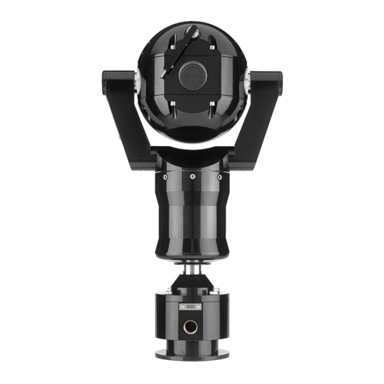
Explosion-protected camera
Hide thumbs
Also See for MIC440AXWUD14636N:
- Specifications (6 pages) ,
- Quick manual (6 pages) ,
- Specifications (6 pages)
Table of Contents
Advertisement
Quick Links
Advertisement
Table of Contents

Related Manuals for Bosch MIC440AXWUD14636N


Summary of Contents for Bosch MIC440AXWUD14636N
- Page 1 MIC440 Explosion-protected Camera MIC440 Operation Manual...
-
Page 2: Table Of Contents
Connection 13.1 Connection Overview 13.2 Connecting the USB to RS-485 Converter Configuration 14.1 Addressing the Camera 14.2 Configuring the Camera for Inverted Operation Operation Maintenance and Troubleshooting 16.1 Cleaning MIC440 Bosch Security Systems, Inc. Operation Manual 2013.11 | 8.1 |... - Page 3 | Table of Contents MIC440 Explosion-protected Camera Technical data Appendices 18.1 MIC440 Common Features by Protocol 2013.11 | 8.1 | Operation Manual Bosch Security Systems, Inc.
-
Page 4: About This Manual
Systems accepts no liability for damage resulting directly or indirectly from faults, incompleteness or discrepancies between the user guide and the product described. Copyright This user manual is the intellectual property of Bosch Security Systems, Inc. and is protected by copyright. All rights reserved. Trademarks All hardware and software product names used in this document are likely to be registered trademarks and must be treated accordingly. -
Page 5: Safety
(NEC)), Canadian Electrical Code, Part I (also called CE Code or CSA C22.1), ® and all applicable local codes. Bosch Security Systems, Inc. accepts no liability for any damages or losses caused by incorrect or improper installation. 2013.11 | 8.1 | Operation Manual Bosch Security Systems, Inc. -
Page 6: Important Notices
– Do not point the camera at the sun. Bosch Security Systems will not be liable for any damage to cameras that have been pointed directly at the sun. –... - Page 7 Please dispose of these devices at your local communal waste collection point or at a recycling center. Environmental statement - Bosch has a strong commitment towards the environment. This unit has been designed to respect the environment as much as possible.
- Page 8 The power supplies have an IP65 rating and are suitable for outside installation; however, for security reasons, Bosch recommends that they are installed in a suitable equipment cabinet. The camera is sealed to IP68 and can be used safely in damp environments or outdoors, as long as the base cable connector is suitably sealed.
- Page 9 Au besoin, l’utilisateur consultera son revendeur ou un technicien qualifié en radio/télévision, qui procédera à une opération corrective. La brochure suivante, publiée par la Commission fédérale des communications (FCC), peut s’avérer utile : How to Identify and Resolve Radio-TV 2013.11 | 8.1 | Operation Manual Bosch Security Systems, Inc.
-
Page 10: Safety Information Specific To Explosion Protection
The camera is designed for use with flammable gases and vapors covered by apparatus groups IIA, IIB, and IIC, and with temperature classes T1 to T6. Bosch Security Systems, Inc. Operation Manual 2013.11 | 8.1 |... -
Page 11: Customer Support And Service
RoHS (Restriction of Hazardous Substances) 2011/65/EC – WEEE (Waste Electrical and Electronic Equipment) 2002/96/EC Customer Support and Service If this unit needs service, contact the nearest Bosch Security Systems Service Center for authorization to return and shipping instructions. Service Centers Telephone: 800-366-2283 or 585-340-4162 Fax: 800-366-1329 Email: cctv.repair@us.bosch.com... -
Page 12: Unpacking
Verify that all the parts listed in the Parts List below are included. If any items are missing, notify your Bosch Security Systems Sales or Customer Service Representative. – Do not use this product if any component appears to be damaged. Please contact Bosch Security Systems in the event of damaged goods. –... -
Page 13: Additional Tools Required
These power supply units are NOT explosion-proof and must be installed outside of the hazardous environment. Additional Tools Required The following table lists additional tools (not supplied by Bosch) that are or may be required to install a MIC camera: Quantity Part... -
Page 14: Product Description
MIC-WKT Washer kit, containing mounting bracket, nozzle, and washer pump drive card. MIC-BP4 Bosch Biphase converter card for MIC power supplies with an available expansion slot. A two-part plastic sunshield to provide additional protection in sunny MIC440SUNSHIELD climates for MIC cameras Comes with stainless steel bosses, washers, and retaining screws. -
Page 15: Installation Of A Mic440 Camera
(24AWG) plus 4 cores of (22 AWG), 2 cores of (24 AWG), and one coax core for the video signal to a maximum distance of 25 m. Warning! Bosch recommends connecting the cable to the unit before taking the unit for mounting on- site. To mount the conduit gland and cable, follow these steps: Remove the 4 x M8 Hexagon bolts holding the conduit adapter (DCA) to the MIC440 unit. -
Page 16: Psu Installation And Setup In A Non-Hazardous Area
For additional protection in hazardous area installations, suitable metal conduit must be used externally for the composite cable run to connect the power supply to the Exd conduit gland (not supplied) in the Deep Conduit Adapter (MIC-DCA). Bosch Security Systems, Inc. Operation Manual 2013.11 | 8.1 |... - Page 17 Exd Barrier Gland (not supplied; to be specified by installer to match incoming conduit) MIC composite cable (length to be specified; 25 m maximum) inside metal conduit (not supplied) MIC PSU Hazardous area Non-Hazardous area Exd Enclosure certified for hazardous areas (not supplied) 2013.11 | 8.1 | Operation Manual Bosch Security Systems, Inc.
-
Page 18: Mic Power Supply Unit Extension
Wire Gauge 18 AWG 16 AWG 14 AWG 12 AWG Maximum Distance in Meters (feet) 46 (151) 73 (240) 116 (381) 185 (606) Maximum Watts, MIC440 = 25.2. Bosch Security Systems, Inc. Operation Manual 2013.11 | 8.1 |... - Page 19 This second box is required to reduce the size of the cable and to reduce the amount of conduit connections to the MIC PSU. Standard MIC composite cable (2 meters MAXIMUM)* inside metal conduit 2013.11 | 8.1 | Operation Manual Bosch Security Systems, Inc.
-
Page 20: Electrical Connections
25 m between the MIC camera and the MIC power supply. For installations that require the camera to be more than 25 m from the power supply, Bosch recommends that a 2 m cable be connected to a junction box (Exd rated for MIC440) from which telemetry, video, and power can be broken out into separate cables and appropriate wiring used to extend the distance to suit. - Page 21 MIC440. The washer connections can be used to operate a relay in the power supply unit, which in turn can activate a pump. 2013.11 | 8.1 | Operation Manual Bosch Security Systems, Inc.
-
Page 22: Select The Mounting Location And Orientation
MIC Series cameras are designed for easy installation in various locations such as directly onto buildings and dedicated CCTV poles. Bosch sells a complete series of mounting brackets designed to allow the camera to achieve the optimal field of view. - Page 23 Figure 7.2: Typical wall mount (from left: Wall Mount Bracket (MIC-WMB), Shallow Conduit Adapter (MIC- SCA), and Spreader Plate (MIC-SPR)) Figure 7.3: Typical corner mount (from left: Wall Mount Bracket (MIC-WMB), Shallow Conduit Adapter (MIC-SCA), and Corner Mount Bracket (MIC-CMB)) 2013.11 | 8.1 | Operation Manual Bosch Security Systems, Inc.
-
Page 24: Select The Mounting Location
If the camera is installed in a highly exposed location where lightning strikes may occur, then Bosch recommends installing a separate lightning conductor within 0.5 m (1.6 ft) of the camera and at least 1.5 m (4.9 ft) higher than the camera. A good earth bonding connection to the camera housing itself will provide protection against damage from secondary strikes. - Page 25 MIC camera - upright, inverted 3. Install the mounting brackets. Observe all appropriate safety precautions and local building regulations. Refer to the MIC Series Mounting Brackets Installation Guide for installation instructions. 2013.11 | 8.1 | Operation Manual Bosch Security Systems, Inc.
-
Page 26: Mount The Camera
Screw the cable connector sleeve onto the plug until it is secured firmly (approximately four (4) turns from the start of thread engagement). Bosch Security Systems, Inc. Operation Manual 2013.11 | 8.1 |... -
Page 27: Earthing The Camera
The PSU "Earth Link" may be used for this purpose. – If dual earthing is unavoidable, then a video isolation transformer should be fitted between the two earths. 2013.11 | 8.1 | Operation Manual Bosch Security Systems, Inc. -
Page 28: Finalize Camera Mounting
The upright unit can be mounted either with the camera ball up or down. So that the picture from a camera installed with the camera ball down appears properly, rotate the camera tilt axis 180°. For more information, see Configuring the Camera for Inverted Operation, page 44. Bosch Security Systems, Inc. Operation Manual 2013.11 | 8.1 |... -
Page 29: Install The Mic Power Supply Unit (Psu)
Use only the power supply specified for your specific model of camera. Bosch provides a range of power supply units (PSUs) for MIC Series cameras. These units have a variety of common voltages and provide all the connections needed for power, telemetry and video. -
Page 30: Fuse Ratings
The figure below displays the layout of the PCB in the MIC PSUs for non-IR cameras, with call- out numbers to the side of or below the connection/terminal ID or the terminal, and ’on’ the fuses. The table below the figure identifies the connections. Bosch Security Systems, Inc. Operation Manual 2013.11 | 8.1 |... - Page 31 Coax connection (Switched visible/thermal video out) BNC socket Video Switched [Not used for MIC440.] Coax connection header BNC socket Video Out (Visible video out) Auxiliary / add-on card terminal Plug in Earth Link Earth Link 2013.11 | 8.1 | Operation Manual Bosch Security Systems, Inc.
-
Page 32: Installation Instructions (Power Supply)
Except for the Earth Link, heater links, and applicable fuses, the MIC PSUs have no user- adjustable parts. MIC cameras have no user-serviceable parts. Caution! Bosch recommends using an uninterruptible power supply (UPS) in connection with a MIC camera/PSU installation. Notice! - Page 33 1. Select a secure installation location for the PSU. Ideally, this is a location where the device cannot be interfered with either intentionally or accidentally. Bosch recommends using an environmentally suitable, lockable equipment cabinet. 2. Locate the four (4) mounting holes of the power supply enclosure.
- Page 34 13. Insert the earth core from the mains cord (item 2 in the figure “Mains input with shield removed…”) into the crimp portion (size M6, UL-certified) of the ring terminal and crimp it in place. Bosch Security Systems, Inc. Operation Manual 2013.11 | 8.1 |...
- Page 35 17. Feed the unconnected end of the shielded composite cable through the top-right M16 cable gland (item 2 in the figure “MIC PSU Enclosure, with cable glands identified”). Figure 11.5: MIC PSU Enclosure, with cable glands identified 2013.11 | 8.1 | Operation Manual Bosch Security Systems, Inc.
- Page 36 20. Tighten the cable gland so that it grips firmly the shielded composite cable. It is important that the braided cable screen engages with the internal clamps of the cable gland to ensure correct EMC protection. Bosch Security Systems, Inc. Operation Manual 2013.11 | 8.1 |...
- Page 37 28. After wiring is complete, connect the power supply to the power source. 29. Verify that the following LEDs are lit: Description LED 2 18 VAC power on to camera LED 4 Power on for optional heater 2013.11 | 8.1 | Operation Manual Bosch Security Systems, Inc.
- Page 38 18 VAC power on camera LED 5 Power on for optional heater 30. Re-attach the enclosure lid and tighten the four (4) captive screws on the cover to ensure that the enclosure is watertight. Bosch Security Systems, Inc. Operation Manual 2013.11 | 8.1 |...
-
Page 39: Fit The Optional Sunshield (Mic440)
Repeat steps three and four for the second half of the sunshield. When fitted properly, both halves of the sunshield should align and meet at the back of the camera head. Figure 12.1: Sunshield and Screws being placed 2013.11 | 8.1 | Operation Manual Bosch Security Systems, Inc. - Page 40 MIC440 Explosion-protected Camera Fit the Optional Sunshield (MIC440) | en Figure 12.2: Side View of Fitted Sunshield Figure 12.3: Back View of Fitted Sunshield Bosch Security Systems, Inc. Operation Manual 2013.11 | 8.1 |...
-
Page 41: Connection
The figure below illustrates how the screw terminal connections on the MIC-USB485CVTR2 connect to the MIC power supply. Depending on the protocol and selected communication mode, you may only need a 2-wire configuration. 2013.11 | 8.1 | Operation Manual Bosch Security Systems, Inc. - Page 42 Black RxB/Rx - Black Full Duplex (4-wire only) RxA/Rx + (Shield) GND/0V (Shield) Shield (always) Green TxA/Tx - Green Simplex Hall Duplex (2-wire) White TxB/Tx + White Full Duplex (4-wire) Bosch Security Systems, Inc. Operation Manual 2013.11 | 8.1 |...
-
Page 43: Configuration
Addressing the camera using Bosch protocol with Camset 4.12.00.06 The camera accepts a custom string of commands that change the camera address. The following procedure uses hexadecimal numbers to identify the camera address. Bosch recommends using a calculator with a decimal to hexadecimal converter to obtain the correct hexadecimal value for the address. -
Page 44: Operation
Off: Clears variable for Address Changing SEE NOTE 1. Pan Reverse On: Pan direction is reversed Off: Pan direction is normal Auto Alarm On: Enables Auto Alarm Off: Disables Auto Alarm Bosch Security Systems, Inc. Operation Manual 2013.11 | 8.1 |... - Page 45 On: Sets Shutter Speed 1/600s (fixed) (1/600s) Off: Returns to Auto Iris Shutter Speed On: Set Shutter Speed 1/1000s (fixed) (1/1000s) Off: Returns to Auto Iris Table 15.1: Bosch OSRD Aux Controls 2013.11 | 8.1 | Operation Manual Bosch Security Systems, Inc.
- Page 46 Operation | en Notes 1. Bosch OSRD camera Address change: The camera address may be changed using the following sequence of commands. This is similar to the “Fast Address” for AUTODOME VG4 model cameras, but utilizes a different set of AUX numbers and there are not any OSD messages displayed during this process.
- Page 47 (Scaled PTZ) Cams Proportional Zoom Off Learn Shot Learn (Scaled PTZ) Cams Start Auto Pan without Go to Limits (Scan) 37 On Stop Auto Pan without Go to Limits 37 Off 2013.11 | 8.1 | Operation Manual Bosch Security Systems, Inc.
- Page 48 Learn Toggle (Pelco D/P) Picture Flip (Mirror) Digital Zoom Enable Learn Learn Operator cannot control (Lock) Digital Zoom Digital Zoom Disable Learn Learn Operator can turn Digital (Unlock) Zoom On/Off Bosch Security Systems, Inc. Operation Manual 2013.11 | 8.1 |...
- Page 49 1) AD 1 tour only; Note Note 211– 50–55 Define Pattern 1 (A0) & Save Pattern (A3) Run Pattern 1 (B0) 2) Bosch one tour only; see AUX 17-20 for options Auto IR On [Enable Learn Learn Learn Night Mode] Auto IR Off [Disable...
- Page 50 32, Learn presets 60,60,32 without moving the camera or sending any other data in between. Inverted/Upright For units mounted like a dome, the left and right is reversed. Set this by learning preset 80 INVERTED Learn Preset 80 UPRIGHT Learn Preset 81 Bosch Security Systems, Inc. Operation Manual 2013.11 | 8.1 |...
- Page 51 To start a scan, GOTO preset 99. To start a frame scan, (5 sec dwell at each end) GOTO preset 98. To stop a scan, Goto preset 96 or move the joystick. 2013.11 | 8.1 | Operation Manual Bosch Security Systems, Inc.
-
Page 52: Maintenance And Troubleshooting
No User-serviceable Parts The device contains no user-serviceable parts. Maintenance and repair of this device shall only be carried out by a Bosch service center. In the event of failure, the device should be removed from site for repair. On-Site Inspection It is recommended that the device be inspected on-site every six months to check mounting bolts for tightness, security, and any signs of physical damage. -
Page 53: Cleaning Mic440
Pre-cleaning Phase: This phase starts 60 seconds before the first cleaning phase. During the Pre-cleaning Phase, an operator can delay the cleaning cycle for five (5) minutes or can cancel this instance of the cleaning cycle. 2013.11 | 8.1 | Operation Manual Bosch Security Systems, Inc. - Page 54 Place the cursor in the AM/PM field and use the arrows to set this parameter. Click Apply. The on-screen display shows the hours and minutes before the start of the cleaning cycle. Bosch Security Systems, Inc. Operation Manual 2013.11 | 8.1 |...
- Page 55 To cancel the cleaning cycle, press the Iris Open or the Iris Close button again, after the delay, during the Pre-Cleaning, or during the Cleaning Phase A. Pressing Iris Open or Iris Close during Cleaning Phase B also cancels the cleaning cycle. 2013.11 | 8.1 | Operation Manual Bosch Security Systems, Inc.
- Page 56 MIC440 Explosion-protected Camera Technical data | en Technical data For product specifications, see the datasheet for your MIC camera, available on the appropriate product pages of the Online Product Catalog at www.boschsecurity.com. Bosch Security Systems, Inc. Operation Manual 2013.11 | 8.1 |...
- Page 57 Digital Zoom control Wiper/Washer Control Wiper ON/Off Washer only Wash/Wipe Combined Misc. Operations Auto pivot (auto flip) Auto Home (Inactivity; preset 1 or tour) Fast Address Capability Maximum Camera Address 2013.11 | 8.1 | Operation Manual Bosch Security Systems, Inc.
- Page 59 Bosch Security Systems, Inc. 850 Greenfield Road Lancaster, PA, 17601 www.boschsecurity.com © Bosch Security Systems, Inc., 2013...
Need help?
Do you have a question about the MIC440AXWUD14636N and is the answer not in the manual?
Questions and answers