Table of Contents
Advertisement
Quick Links
Advertisement
Table of Contents

Related Manuals for Autool LM708


Summary of Contents for Autool LM708
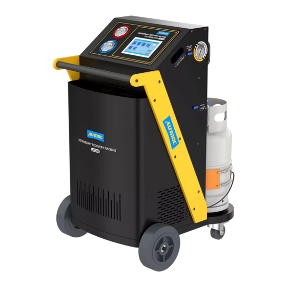
- Page 1 AUTOOL LM708 Refrigerant Recovery Machine User Manual 用户手册 www.autooltech.com...
- Page 3 COPYRIGHT INFORMATION ● Copyright All rights reserved by AUTOOL TECH. CO., LTD. No part of this publication may be reproduced, stored in a retrieval system, or transmitted in any form or by any means, electronic, mechanical, photocopying, recording or otherwise, without the prior written permission of AUTOOL.
-
Page 4: Table Of Contents
TABLE OF CONTENTS Cautions ......................2 General safety....................2 Product Introduction ..................3 Overview ......................3 Specifications ....................3 Function table....................4 Product Structure ....................5 Structure diagram.................... 5 Operations Instruction ..................7 Unlock load cells ..................... 7 Fill equipment with refrigerant ................. 7 Non-condensable purge.................. -
Page 5: Cautions
CAUTIONS General For the correct use of the instrument, please read the full text safety of this manual carefully before use. The storage cylinder in this unit contains liquid refrigerant. Overfilling of the cylinder can cause violent explosion. Do not disable the overfill safety feature. -
Page 6: Product Introduction
PRODUCT INTRODUCTION ● Overview LM-708 is an ideal option for workshops that have require- ments of handling both R-134a and HFO-1234yf refrigerants. The loss of refrigerant is minimized to less than 50 gram at shifting from one refrigerant to another, and deep internal evacuation ensures zero cross contamination between two refrigerants. -
Page 7: Function Table
After power witch is turned on, the Pre-ventilation machine makes 30 seconds ventilation, before it is powered on. Dual condensers and cooling fans, one for R-134a, one for HFO-1234yf. Automatic service reminding. The equipment filter-drier life is designed to desiccate and recycle 100 KG refrigerant. -
Page 8: Product Structure
PRODUCT STRUCTURE Structure diagram Touch screen HP gauge LP gauge R-134a tank gauge Non-condensable purge valve for R-134a tank... - Page 9 Power switch Fuse USB interface Power cable HFO-1234yf Coupler New oil bottle connect fittings R-134a refrigerant tank HFO-1234yf tank gauge Non-condensable R-134a Coupler purge valve for connect fittings HFO-1234yf tank HFO-1234yf Used oil bottle Refrigerant tank...
-
Page 10: Operations Instruction
OPERATIONS INSTRUCTION ● Unlock Remove the two lock bolts, to release load cells of the two load cells tanks, and to make them ready to work. Warning Failure to remove the load cell lock bolts may cause wrong refrigerant processing amount. When you need transport the machine, please screw those bolts on. -
Page 11: Non-Condensable Purge
● Through tank fittings, connect either HP or LP hose with exter- nal refrigerant R-134a or HFO-1234yf, and turn on the machine, select “Tank fill” function, set tank fill amount to fill R-134a or HFO-1234yf tank with refrigerant. ● It is recommended to maintain refrigerant level of both tanks at 4-6kg. - Page 12 Suction Charge ● When machine is switched on, filter-drier life is displayed. Click OK to enter main menu. Total refrigerant recovered: 15.85Kg / 34.76Lb Refrigerant can be recovered till filter-drier change: 84.15Kg / 185.02Lb Change filter-drier ● Main menu. ( in right-upper part the weight of other refrigerant is displayed)
-
Page 13: Recovery
● Recovery Empty used oil vessel before the recovery function is started. ● Select “Recovery” function icon and press ENTER to start the process. ● The recovery process recovers the refrigerant from vehicle A/C system, until vacuum degree is achieved in the vehicle A/C system. -
Page 14: Tank Fill
flush before oil injection and refrigerant charging is a must. ● You can manually set charge amount with volume, or select “Charge by database” to set charge amount by car make and model. ● You can choose to charge through high side, low side or both sides. -
Page 15: System Setting
● You can select “Auto.mode” to do full cycle of, recovery, vacuum and charge. ● According the vehicle being serviced, select “Normal charging” (Fuel vehicles) or “High voltage charging” (Hybrid or electric vehicles). In normal charging mode, hose flush (flush with liquid refrigerant to remove the oil residue inside the service hoses) is optional;... - Page 16 ● Unit set: To set metric or American imperial unit. The two numbers displayed in the bottom part of the interface are values of two tank load cells, for load cell diagnosis purpose. ● Empty container weight set: The total load cell reading equals the sum of empty container weight and net refrigerant content value.
-
Page 17: Main Troubleshooting
MAIN TROUBLESHOOTING Malfunction Reasons Solution ● ● Insufficient vacuum pump Add oil to central line. ● oil. Put new oil. ● ● Pump oil emulsion, dirty. Clean oil inlet. Low vacuum ● ● Pump oil inlet plugged. Check connection. degree. ●... - Page 18 Malfunction Reasons Solution ● ● While auto Low pressure switch plug Fasten low pressure switch plug. disconnected from PCA A/C has socket. refrigerant, equipment displays alarm 005. ● ● High pressure High pressure switch Fasten high pressure switch plug disconnected from plug.
- Page 19 Malfunction Reasons Solution ● ● The contact between Remove solenoid #2 from valve solenoid valve #2 and base, clean the solenoid valve valve base is not well and valve base. sealed. During vacuum, there is suction in old oil bottle. Remarks: Regular maintenance by specialized technicians may largely reduce machine failure.
-
Page 20: Maintenance Service
MAINTENANCE SERVICE Our products are made of long-lasting and durable materials, and we insist on perfect production process. Each product leaves the factory after 35 procedures and 12 times of testing and inspec- tion work, which ensures that each product has excellent quality and performance. -
Page 21: Warranty
Disclaimer All information, illustrations, and specifications contained in this manual, AUTOOL resumes the right of modify this manual and the machine itself with no prior notice. The physical appearance and color may differ from what is shown in the manual, please refer to the actual product. -
Page 22: Return & Exchange Service
RETURN & EXCHANGE SERVICE ● If you are an AUTOOL user and are not satisfied with the Return & AUTOOL products purchased from the online authorized Exchange shopping platform and offline authorized dealers, you can return the products within seven days from the date of receipt;...
Need help?
Do you have a question about the LM708 and is the answer not in the manual?
Questions and answers