Table of Contents
Advertisement
Quick Links
Advertisement
Table of Contents

Related Manuals for Gewiss Chorus GW 10 795


Summary of Contents for Gewiss Chorus GW 10 795
- Page 1 Termostato KNX - da incasso KNX thermostat - flush-mounting Thermostat KNX - à encastrer Termostato KNX - de empotrar KNX-Thermostat - für den Unterputz GW 10 795 GW 12 795 GW 14 795 MANUALE DI PROGRAMMAZIONE PROGRAMMING MANUAL - MANUEL DE PROGRAMMATION MANUAL DE PROGRAMACIÓN - PROGRAMMIERHANDBUCH...
-
Page 3: Table Of Contents
CONTENTS page GENERAL DESCRIPTION Briefly .............4 Position of the commands . -
Page 4: General Description
www.gewiss.com. -
Page 5: Position Of The Commands
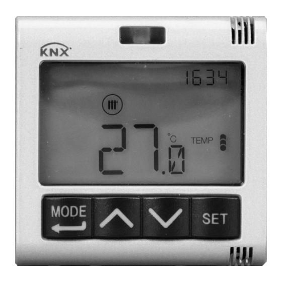
GENERAL DESCRIPTION Position of the commands The thermostat is equipped with a backlit LCD display and four command push-buttons that can always be accessed. -
Page 6: Description Of The Commands
GENERAL DESCRIPTION Description of the commands COMMAND PUSH-BUTTONS Symbol Select operating mode / Confirm Adjust temperature (+) / Visualise pages Adjust temperature (-) / Visualise pages Setting the parameters INFORMATION ON THE DISPLAY Clock / KNX temperature adjustment probe visualised Settings menu / Set the values to send to the KNX temperature adjustment probe Heating activation 1°... -
Page 7: Control Modes
GENERAL DESCRIPTION Control modes The thermostat can be set with 2 different control modes: • Slave: the functioning depends on the device configured as the Master (e.g. the GW1x794 KNX flush-mounting timed thermostat), that sets the type, operating mode or set-point of the thermostat on the basis of the ETS parameterisation. In the first case (modes), the thermostat uses the set-points configured via ETS. - Page 8 GENERAL DESCRIPTION MEANING OF Heating Air-conditioning Symbol Operating Operating Set-point Set-point modes modes Economy Comfort ECONOMY COMFORT Pre-comfort Pre-comfort COMFORT COMFORT Comfort Economy COMFORT ECONOMY The anti-freeze function is only active in heating mode, when the temperature adjustment system is switched OFF. In this case, the thermostat uses the fixed anti-freeze temperature set-point, only reactivating the heating system if the room temperature falls below T...
- Page 9 GENERAL DESCRIPTION During operation, the activation of heating or conditioning mode is indicated in the following way: Heating symbol indicates that the activation command has been sent to the command actuator of the boiler or area solenoid valve (1° stage of the heating system ).
-
Page 10: User Instructions
USER INSTRUCTIONS Thermostat operation statuses The thermostat has two distinct operation statuses: - Normal operation - Parameter setting When it is switched on, the thermostat goes into "normal operation" status. Using the button key, you can switch from one status to the other (the switchover from "parameter setting"... - Page 11 USER INSTRUCTIONS Forcing the set-point manually If the visible page relates to the thermostat and any HVAC mode other than OFF is active, press the button key to temporarily modify the set-point of the active HVAC mode (within the adjustment limits set via ETS), then confirm with button key or wait for the 5-second time-out period to elapse.
-
Page 12: Parameter Setting
USER INSTRUCTIONS Pages relating to the remote elements Viewing the remote elements If the visible page relates to a remote element, press the button key to alternate the visualisation of the detected temperature and the set-point; if one of these two figures is not available, nothing will happen when the button key is pressed. - Page 13 USER INSTRUCTIONS Setting GMT / daylight-saving time Use the button key to choose either GMT or daylight-saving time (OFF = GMT; ON = daylight-saving time). This screen is only visible if the parameter has been enabled from ETS. To confirm your choice and move on to the next parameter, press the button key within 30 seconds.
- Page 14 USER INSTRUCTIONS Back-lighting timing Use the button key to set the minimum duration of the inactivity time of the user before the back-lighting is automatically deactivated (the gap can be set from 10 to 180 seconds). This parameter is only visible if the back- lighting is active.
- Page 15 USER INSTRUCTIONS The figure shows that as long as the detected temperature is below the heating set-point, the operating mode is "heating"; if the detected value is higher than the air- Air-conditioning conditioning set-point, then the operating mode is "air-conditioning". If the detected value is within the interdiction area, the operating mode remains as before.
- Page 16 USER INSTRUCTIONS If the operating type is "air-conditioning": Setting the set-point (air-conditioning) When the symbol appears, the temperature value begins flashing. Adjust the value of ) with COMFORT the aid of the button keys. To confirm the set value, press the button key within 30 seconds.
- Page 17 USER INSTRUCTIONS Control parameters The screens that can be visualised will depend on the type of control logic of the temperature adjustment system that was set via ETS (with the “Heating control algorithm” and the “Air-conditioning control algorithm” parameters of the “Load control” menu): •...
- Page 18 USER INSTRUCTIONS TWO POINTS 0%-100% The operating principle is similar to that of the two points ON-OFF, but with the difference that the communication objects for temperature adjustment management are of 1 byte. In heating mode, when the detected temperature is lower than the “set-point - ”...
- Page 19 USER INSTRUCTIONS PWM PROPORTIONAL-INTEGRAL The PWM control algorithm, used to control the temperature adjustment system, allows you to drastically reduce the times subject to thermal inertia and introduced by the two- point control. This type of control involves the modulation of the impulse duty-cycle, represented by the temperature adjustment system activation time, on the basis of the difference between the fixed set-point and the temperature effectively detected.
- Page 20 USER INSTRUCTIONS The device keeps the temperature adjustment system switched on for a cycle time percentage that depends on the output function of the proportional-integral control; the device continually adjusts the system, modulating the system ON-OFF times with a duty- cycle that depends on the value of the output function (calculated at each time gap equal to the cycle time).
- Page 21 USER INSTRUCTIONS Two components are needed to calculate the output function: the proportional component and the integral component, used to improve the response in order to reach the temperature at the fixed set-point. Once the proportional band has been defined (from set-point to set-point for heating mode, from set-point to set-point + for air-conditioning mode), its width determines the extent of the system's response: if it is too narrow, the system will be...
- Page 22 USER INSTRUCTIONS FAN COIL WITH ON-OFF SPEED CONTROL The operating principle involves activating/deactivating the fan coil speeds on the basis of the difference between the fixed set-point and the detected temperature, using independent 1- bit communication objects to manage the individual speeds. The figures below refer to the control of the speeds of a fan coil with three operating stages for heating and air-conditioning.
- Page 23 USER INSTRUCTIONS Speed V1 is activated when the temperature value is lower than the “set-point - valve ” value (in heating mode) or higher than the “set-point + ” value 1heat valve 1cond (in air-conditioning mode), and deactivated when the temperature value reaches the “set-point ”...
- Page 24 USER INSTRUCTIONS FAN COIL WITH CONTINUOUS SPEED CONTROL The operating principle is similar to that of the fan coil with ON-OFF speed control, but with the difference that there are no independent communication objects for managing the individual speeds - just one 1-byte object. The figures below refer to the control of the speeds of a fan coil with three operating stages for heating and air-conditioning.
- Page 25 USER INSTRUCTIONS Speed V1 is activated when the temperature value is lower than the “set-point - valve ” value (in heating mode) or higher than the “set-point + ” value 1heat valve 1cond (in air-conditioning mode), and deactivated (sending of “fan OFF” value) when the temperature value reaches the “set-point - ”...
- Page 26 USER INSTRUCTIONS Setting the valve adjustment differential Use the button keys to set the value of the adjustment differential of the fan coil valve control algorithm (the gap can be set from 0,1°C to 2,0°C). If the control logic is common, the parameter remains the same in both heating and air-conditioning mode.
- Page 27 USER INSTRUCTIONS Setting the inertia for speed 3 Use the button key to set the value of the inertia time for the fan coil speed 3 (the gap can be set from 0 to 10 seconds). This parameter is visible if the fan coil speed number is 3. To confirm your choice and move on to the next parameter, press the button key within 30 seconds.
- Page 28 USER INSTRUCTIONS Parameter setting of remote elements From the thermostat display, you can modify the parameters relating to the general remote element. The screens of the Set menu of the individual remote element are shown below. Repeat the programming for all the remote elements (P01, P02, P03, P04) that are present. To access the parameter setting pages for the remote elements, start from the visualisation screen of the required element (see par.
-
Page 29: Pre-Set Parameters
USER INSTRUCTIONS Pre-set parameters Time 0.00 16 °C 18 °C Heating temperature set-point 20 °C 5 °C ANTI FREEZE 24 °C 26 °C Air-conditioning temperature set-point 28 °C 35 °C HIGH TEMPERATURE PROTECTION Temperature measurement unit °C common, Control logic 2 ON-OFF points Adjustment differential 0,2 °C... - Page 30 According to article 9 paragraph 2 of the European Directive 2004/108/EC, the responsible for placing the apparatus on the Community market is: GEWISS S.p.A Via A. Volta, 1 - 24069 Cenate Sotto (BG) Italy Tel: +39 035 946 111 Fax: +39 035 945 270 E-mail: qualitymarks@gewiss.com +39 035 946 111 sat@gewiss.com...
Need help?
Do you have a question about the Chorus GW 10 795 and is the answer not in the manual?
Questions and answers