Table of Contents
Advertisement
Quick Links
Advertisement
Table of Contents

Related Manuals for Gewiss GW 10 761


Summary of Contents for Gewiss GW 10 761
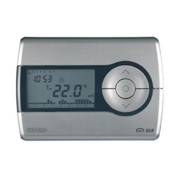
- Page 1 Easy timed thermostat GW 10 761 GW 14 761 Technical Manual...
-
Page 2: Table Of Contents
Summary Introduction ..............................3 Application ..............................4 Limits to the associations ........................4 “Settings” menu ............................5 Parameters ............................5 Communication objects ........................6 “Control algorithm” menu ........................... 8 ... -
Page 3: Introduction
1 Introduction This manual describes the functions of the devices named GW1x761 “Easy timed thermostat” and how to use the ETS configuration software to change the settings and configurations. -
Page 4: Application
2 Application The Easy timed thermostat is a device that manages the HVAC system. It is able to regulate the temperature in the environment in which it is installed, using the KNX/EIB system to manage the actuators that control the solenoid valves, boilers etc that comprise the heating and air-conditioning systems. -
Page 5: "Settings" Menu
3 “Settings” menu Here it is possible to configure the programming mode between ETS mode (S-Mode) and Easy mode by the Easy controller software (Kit GW90837, Kit GW90838, GW90840) see Diag 3.1. Diag. 3.1 Parameters 3.1.1 Programming mode This parameter determines the programming mode of the device: •... -
Page 6: Communication Objects
Communication objects The Settings menu makes the following communication objects visible (see Diag. 3.2.): Diag. 3.2 3.2.1 HVAC mode output This allows the device to send HVAC mode update bus telegrams to the slave devices. When the operating mode is modified on the “master” device, the device sends a bus telegram through this object to the “slave”... - Page 7 3.2.5 Operating type input Here you can configure the remote control of the device operating type by bus command. When this communication object receives a telegram with "1” a logic value, the device sets the operating type to Heating, indicated by a pilot light on the display, maintaining the same operating mode as before; vice versa, when this communication object receives a telegram with a "0"...
-
Page 8: "Control Algorithm" Menu
4 “Control algorithm” menu The Control algorithm menu lists all the parameters used to set the control algorithms for the heating and air conditioning system; the structure and the options displayed in the Control algorithm menu change according to the settings for the Control type parameters. Parameters If the control type selected is two points control (On/Off), the menu is shown in diag.4.1. - Page 9 HEATING ΔT AIR CONDITIONING ΔT Diag. 4.2 You can see in this diagram that there are two thresholds which control the ON and OFF commands for the heating system and two for air conditioning system; for heating system, the first threshold consists in the “setpoint- “...
- Page 10 minute until it receives due confirmation from the load; the heating/air conditioning system pilot light will blink to signal this anomaly. The Heating status feedback and the Air cooling status feedback communication objects are visible. 4.1.5 Thermal gradient autostoring (only Heating) This enables the thermal gradient autostoring function so that the device which operates in AUTO mode can bring the ambient temperature to full capacity before the mode switch set by the daily timer profile is implemented.
- Page 11 • PI control (PWM) The algorithm used to control the heating system is the algorithm which allows you to reduce heat inertia times caused by a two points control, called a PMW control. This control type foresees the modulation of the pulse duty-cycle, represented by the heating (or air conditioning) system activation time, according to the difference between the indicated setpoint and the detected temperature (see Diag.
- Page 12 With this setting, the Cycle time and PWM regulation differential parameters for heating and air conditioning are visible. 4.1.7 Cycle time - Heating Here it is possible to set the time within which the device must perform PWM modulation. The settings are provided in the drop-down menu (an interval of from 5 to 60 minutes).
-
Page 13: Communication Objects
Communication objects The Control algorithm menu makes the following communication objects visible (see Diag. 4.6.): Diag. 4.6 4.2.1 Heating status feedback This allows the device to be informed on the status of the actuator that manages the heating system controlled by the timed thermostat; once the command has been sent to this actuator, if the device does not receive confirmation within one minute that the load has executed the command by bus telegram to the communication object in question, it will instantly send the command again every minute until it receives due confirmation from the load. -
Page 14: "Temperature Setpoint" Menu
5 “Temperature setpoint” menu The Temperature setpoint menu lists all the parameters needed to configure the setpoint values for the various HVAC modes and the two different operating types (see diag. 5.1). Please remember that among the various setpoints belonging to the same function type, there is a setting value threshold determined from what seen below: ≤... -
Page 15: Communication Objects
5.1.3 High temperature protection setpoint - Air conditioning Here you can set the setpoint value for the OFF mode when it is AIR CONDITIONING operating mode; the values range from 300 (30 degrees centigrade) to 400 (40 degrees centigrade). The restrictions listed before must be complied with when setting this value. This value can in any case be modified by the operator using the setting in the local navigation menu on the device. -
Page 16: "Scenes Management" Menu
6 “Scenes management” menu Here is possible to enable the scene functions used by the device (see Diag. 6.1). Diag. 6.1 6.1 Parameters 6.1.1 Activate function This is to enable the scene function and make the relative Scene communication object visible. The scene function sends two possible commands to the device: −... -
Page 17: Communication Objects
Communication objects The Scenes management menu makes the following communication objects visible (see Diag. 6.2.): Diag. 6.2 6.2.1 Scene Using this communication object, the device is able to receive the execute and store scene commands from the bus. On receiving a store scene command, through a bus telegram to the communication object in question, please remember that the device memorises the HVAC mode, operating type and any temporary forced setpoint.
Need help?
Do you have a question about the GW 10 761 and is the answer not in the manual?
Questions and answers