Table of Contents
Advertisement
Quick Links
Termostato T+H Easy - da incasso
Easy T+H thermostat - flush-mounting
Thermostat T+H Easy - à encastrer
Termostato T+H Easy - de empotrar
Thermostat T+H Easy - für den Unterputz
GW 10 765H
GW 12 765H
GW 14 765H
MANUALE DI PROGRAMMAZIONE
PROGRAMMING MANUAL - MANUEL DE PROGRAMMATION
MANUAL DE PROGRAMACIÓN - PROGRAMMIERHANDBUCH
Advertisement
Table of Contents

Related Manuals for Gewiss Chorus GW 10 765H


Summary of Contents for Gewiss Chorus GW 10 765H
- Page 1 Termostato T+H Easy - da incasso Easy T+H thermostat - flush-mounting Thermostat T+H Easy - à encastrer Termostato T+H Easy - de empotrar Thermostat T+H Easy - für den Unterputz GW 10 765H GW 12 765H GW 14 765H MANUALE DI PROGRAMMAZIONE PROGRAMMING MANUAL - MANUEL DE PROGRAMMATION MANUAL DE PROGRAMACIÓN - PROGRAMMIERHANDBUCH...
-
Page 3: Table Of Contents
CONTENTS page GENERAL DESCRIPTION Briefly .............4 Position of the commands . -
Page 4: General Description
More information about the programming of the thermostat with the Easy Configurator is given in the Programming Manual of Easy devices with Easy Controller (which can be downloaded from the website www.gewiss.com). -
Page 5: Position Of The Commands
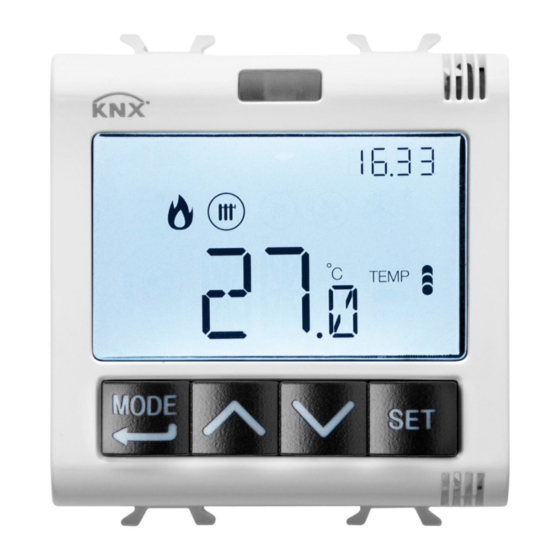
GENERAL DESCRIPTION Position of the commands The thermostat is equipped with a backlit LCD display and four command push-buttons that can always be accessed. ATTENTION! If the display backlighting is enabled, only the screen will light up when any one of the 4 front button keys is pressed for the first time;... -
Page 6: Description Of The Commands
GENERAL DESCRIPTION Description of the commands COMMAND PUSH-BUTTONS Symbol Select operating mode / Confirm Adjust temperature (+) / Visualise pages Adjust temperature (-) / Visualise pages Parameter setting INFORMATION ON THE DISPLAY Clock / KNX temperature adjustment probe visualised / Value shown on the humidity page (Hr = relative humidity;... -
Page 7: Control Modes
GENERAL DESCRIPTION Control modes The thermostat can be set with 2 different control modes: • Slave: operation depends on the device configured as the Master (e.g. the Easy flush- mounting timed thermostat GW1x764H), which decides the type, operating mode or setpoint of the thermostat. -
Page 8: Operating Mode
GENERAL DESCRIPTION MEANING OF Heating Cooling Symbol Setpoint Operating mode Setpoint Operating mode Economy Comfort ECONOMY COMFORT Pre-comfort Pre-comfort COMFORT COMFORT Comfort Economy COMFORT ECONOMY The anti-freeze function is only active in heating mode, when the temperature adjustment system is switched OFF. In this case, the thermostat uses the fixed high temperature temperature setpoint, only reactivating the heating system if the room temperature falls below (T... -
Page 9: Thermostat Operation Statuses
GENERAL DESCRIPTION During operation, the activation of the heating or cooling mode is indicated in the following way: Heating symbol indicates that the activation command has been sent to the command actuator of the boiler or area solenoid valve. If the thermostat does not receive confirmation of effective implementation from the actuator, symbol will begin to flash. -
Page 10: User Instructions
USER INSTRUCTIONS Normal operation In normal operation conditions, the pages containing information about the thermostat are shown. If the sections relating to humidity have been enabled, and if at least one remote element is present (e.g. Easy temperature adjustment probes), the relevant pages are also visualised. - Page 11 USER INSTRUCTIONS or wait for the 5-second time-out period to elapse. The use of forcing is indicated by the flashing of the , , symbols. It remains active until the active HVAC mode is modified. Pages relating to the thermostat (control type: setpoint) Forcing the setpoint manually If the displayed page relates to the thermostat, and the control type has been set in setpoint, press the...
- Page 12 USER INSTRUCTIONS Pages relating to the remote elements Viewing the remote elements If the visible page relates to a remote element, press the button key to alternate the visualisation of the detected temperature and the setpoint; if one of these two figures is not available, nothing will happen when the button key is pressed.
- Page 13 USER INSTRUCTIONS Parameter setting To set the operating parameters of the thermostat, humidity, and any remote elements (e.g. Easy temperature adjustment probes), press the button key. To quit the parameter setting procedure without saving the modifications made on the current page, just press the button key twice or wait 30 seconds from the last pressure on the button keys.
- Page 14 USER INSTRUCTIONS Returning to the main page Use the button key to set the main page that the device must automatically visualise at the end of a period of inactivity by the user (OFF = function disabled; THER = main thermostat page;...
- Page 15 USER INSTRUCTIONS Back-lighting timing Use the button key to set the minimum duration of the inactivity time of the user before the back-lighting is automatically deactivated (the gap can be set from 10 to 180 seconds). This parameter is only visible if the back- lighting is active.
- Page 16 USER INSTRUCTIONS Setting the alarm threshold temperature Use the button key to set the maximum floor-level temperature above which the thermostat suspends heating to prevent any possible damage (the value is expressed as tenths of °C, and can be set from 150 to 1000 in steps of 100).
- Page 17 USER INSTRUCTIONS Operating parameters White balancing Use the button keys to set the weight of the red component (RED) in the backlighting of the display (value can be set between 1 and 63). The regulation only applies to the white colour of the screen. To confirm the selection and continue with the next parameter, press the button key within 30 seconds.
- Page 18 USER INSTRUCTIONS If the displayed page relates to the thermostat (type of operation: heating) Setpoint setting When the symbol appears, the temperature value begins flashing. Adjust the value of (Teconomy) / with the aid of the button keys. To confirm the set value, press the button key within 30 seconds.
- Page 19 USER INSTRUCTIONS If the displayed page relates to the thermostat (type of operation: cooling) Setpoint setting When the symbol appears, the temperature value begins flashing. Adjust the value of ) with COMFORT the aid of the button keys. To confirm the set value, press the button key within 30 seconds.
- Page 20 USER INSTRUCTIONS If the displayed page relates to humidity Humidity thresholds (from 1..5) Use the button keys to modify the value of the relative humidity thresholds (up to 5, if enabled). The gap that can be set varies from 1% to 100%. To confirm the set value and move on to the next parameter, press the button key within 30 seconds.
- Page 21 USER INSTRUCTIONS TWO POINTS ON-OFF The operating principle manages the temperature adjustment system with two thresholds (hysteresis cycle), used to distinguish the ON or OFF status of the system. In heating mode, when the detected temperature is lower than the “setpoint - ”...
- Page 22 USER INSTRUCTIONS PWM PROPORTIONAL-INTEGRAL The PWM control algorithm, used to control the temperature adjustment system, allows you to drastically reduce the times subject to thermal inertia and introduced by the two- point control. This type of control involves the modulation of the impulse duty-cycle, represented by the temperature adjustment system activation time, on the basis of the difference between the fixed setpoint and the temperature effectively detected.
- Page 23 USER INSTRUCTIONS The device keeps the temperature adjustment system switched on for a cycle time percentage that depends on the output function of the proportional-integral control; the device continually adjusts the system, modulating the system ON-OFF times with a duty- cycle that depends on the value of the output function (calculated at each time gap equal to the cycle time).
- Page 24 USER INSTRUCTIONS FAN COIL WITH ON-OFF SPEED CONTROL The operating principle involves activating/deactivating the fan coil speeds on the basis of the difference between the fixed setpoint and the detected temperature, using independent 1-bit communication objects to manage the individual speeds. The figures below refer to the control of the speeds of a fan coil with three operating stages for heating and cooling.
- Page 25 USER INSTRUCTIONS Speed V1 is activated when the temperature value is lower than the “setpoint - valve ” value (in heating mode) or higher than the “setpoint + ” value 1heat valve 1cond (in cooling mode), and deactivated when the temperature value reaches the “setpoint - ”...
- Page 26 USER INSTRUCTIONS Setting the valve adjustment differential Use the button keys to set the value of the adjustment differential of the fan coil valve control algorithm (the gap can be set from 0.1°C to 2.0°C). If the control logic is common, the parameter remains the same in both heating and cooling mode.
- Page 27 USER INSTRUCTIONS Setting the inertia for speed 3 Use the button key to set the value of the inertia time for fan coil speed 3 (the gap can be set from 0 to 10 seconds). To confirm your choice and move on to the next parameter, press the button key within 30 seconds.
-
Page 28: Setting The Parameters
USER INSTRUCTIONS Setting the parameters of the remote elements From the thermostat display, you can modify the parameters relating to the general remote element. The screens of the Set menu of the individual remote element are shown below. Repeat the programming for all the remote elements (P01, P02, P03, P04) that are present. To access the pages for setting the parameters of the remote elements, start from the visualisation screen of the required element (see Choosing the page you want to see - page 10), then press the... -
Page 29: Easy Channel Localisation Mode
USER INSTRUCTIONS Easy channel localisation mode To access the Easy channel localisation mode, start from the thermostat normal operation screen and press the button key twice (the “Enabling supplementary parameter pages” menu must be set on GFC). In this way you can localise the channels implemented by the device, to insert them in the various functions created with the Easy configurator (Easy Controller). - Page 30 USER INSTRUCTIONS CDC (Cooling command) Used to send the ON/OFF command to the Easy actuators that control the solenoid valve of the cooling system. HS1 (Speed 1 of heating fan coil) Used to send the ON/OFF command to the channel of the Easy actuator that controls speed 1 of the heating fan coil.
- Page 31 USER INSTRUCTIONS SE1 (Temperature adjustment probe 1) Used to control remote device 1 (Easy temperature adjustment probe). SE2 (Temperature adjustment probe 2) Used to control remote device 2 (Easy temperature adjustment probe). SE3 (Temperature adjustment probe 3) Used to control remote device 3 (Easy temperature adjustment probe).
-
Page 32: Pre-Set Parameters
USER INSTRUCTIONS Pre-set parameters Time 0.00 16 °C 18 °C Heating temperature setpoint 20 °C 5 °C ANTI FREEZE 24 °C 26 °C Cooling temperature setpoint 28 °C 35 °C HIGH TEMPERATURE PROTECTION Temperature measurement unit °C common, Control logic 2 ON-OFF points Adjustment differential 0.2°C... - Page 33 USER INSTRUCTIONS F.A.Q. What does the temperature value on the display actually represent? If no external temperature probe is enabled during programming, the value on the display is the temperature detected by the sensor built into the thermostat. If, however, an external temperature probe (of the Easy or NTC type) has been enabled, the thermostat shows the average of the values detected by the probe and the sensor, using a variable weight between 10% and 100% (which can be defined via Easy configurator).
- Page 34 USER INSTRUCTIONS What happens to the time band set on the thermostat if the BUS power supply fails and is reset? The thermostat has no buffer battery, so the time setting is lost if there is a BUS voltage failure. The time can only be reset manually. Is it possible to understand whether the potential-free contact input is open or closed? The thermostat display shows whether the contact is closed...
- Page 36 According to article 9 paragraph 2 of the European Directive 2004/108/EC, the responsible for placing the apparatus on the Community market is: GEWISS S.p.A Via A. Volta, 1 - 24069 Cenate Sotto (BG) Italy Tel: +39 035 946 111 Fax: +39 035 945 270 E-mail: qualitymarks@gewiss.com +39 035 946 111 sat@gewiss.com...
Need help?
Do you have a question about the Chorus GW 10 765H and is the answer not in the manual?
Questions and answers