Table of Contents
Advertisement
Quick Links
Advertisement
Table of Contents

Related Manuals for Gewiss Chorus GW 10 763


Summary of Contents for Gewiss Chorus GW 10 763
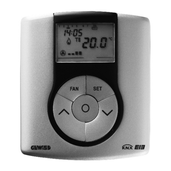
- Page 1 Easy thermostat GW 10 763 GW 14 763 Technical Manual...
-
Page 2: Table Of Contents
Summary Introduction ..............................3 Application ..............................4 Limits to the associations ........................4 “Settings” menu ............................5 Parameters ............................5 Communication objects ........................5 “Main” menu ............................... 6 ... -
Page 3: Introduction
1 Introduction This manual describes the functions of the devices named GW1x763 “Easy thermostat” and how to use the ETS configuration software to change the settings and configurations. -
Page 4: Application
2 Application The Easy thermostat allows you to manage the temperature in the area it is installed in. The temperature is regulated by the KNX/EIB actuators which are managed by the Home Automation KNX/EIB bus and control the heating or air conditioning elements, including the fan coils. When combined with the wall Easy Timer Thermostat (GW 10 761 - GW 14 761), from which it receives the operation type and mode via the bus, it is possible to create multi-zone thermal regulation systems. -
Page 5: "Settings" Menu
3 “Settings” menu Here it is possible to configure the programming mode between ETS mode (S-Mode) and Easy mode by the Easy controller software (Kit GW90837, Kit GW90838, GW90840) see Diag 3.1. Diag. 3.1 Parameters 3.1.1 Programming mode This parameter determines the programming mode of the device: •... -
Page 6: "Main" Menu
4 “Main” menu The Main menu lists all the parameters needed to configure the behaviour of the device in HVAC system (see Diag. 4.1); the structure and the options displayed in the Main menu change according to the settings for the various options. Diag. - Page 7 With this setting, the Operating type and mode command execution parameter appears, which will be analysed in paragraph 4.1.2. 4.1.2 Operating type and mode command execution: This enables the device to receive the HVAC mode and operating type setting commands from the bus; the settings are: •...
-
Page 8: Communication Objects
Communication objects The Main menu makes the following communication objects visible (see Diag. 4.2.): Diag. 4.2 4.2.1 HVAC mode input Here you can configure the remote control of the device operating mode (HVAC mode) by bus command. When this communication object receives a telegram with the operating mode information that is to be set, the device sets the operating mode according to the command received, indicated by a pilot light on the display. -
Page 9: "Temperature Setpoint" Menu
5 “Temperature setpoint” menu The Temperature setpoint menu lists all the parameters needed to configure the setpoint values for the various HVAC modes and the two different operating types (see diag. 5.1). Please remember that among the various setpoints belonging to the same function type, there is a setting value threshold determined from what seen below: ≤... -
Page 10: Communication Objects
5.1.2 Heating antifreeze setpoint: (tenth of °C) Here you can set the setpoint value for the OFF mode when it is HEATING operating mode; the values range from 20 (2 degrees centigrade) to 70 (7 degrees centigrade). The restrictions listed before must be complied with when setting this value. This value can in any case be modified by the operator using the setting in the local navigation menu on the device (if setpoint modification via keyboard is enabled). -
Page 11: "Control Algorithm" Menu
6 “Control algorithm” menu The Control algorithm menu lists all the parameters used to set the control algorithms for the heating and air conditioning system; the structure and the options displayed in the Control algorithm menu change according to the settings for the Control type parameter. Parameters If the control type selected is two points control (On/Off), the menu is shown in diag. - Page 12 HEATING ΔT AIR CONDITIONING ΔT Diag. 6.2 You can see in this diagram that there are two thresholds which control the ON and OFF commands for the heating system and two for air conditioning system; for heating system, the first threshold consists in the “setpoint- “...
- Page 13 minute until it receives due confirmation from the load; the heating/air conditioning system pilot light will blink to signal this anomaly. The Heating status feedback and the Air cooling status feedback communication objects are visible. If the control type selected is PI control (PWM), the menu is shown in Diag. 6.3. 6.1.5 Control type: PI control (PWM) Diag.
- Page 14 HEATING set point set point-ΔT cycle time Diag. 6.4 AIR CONDITIONING set point+ΔT set point cycle time Diag. 6.5 With this setting, the Cycle time for heating control, Cycle time for air conditioning control, Heating regulation proportional differential (tenth of °C) and Air conditioning regulation proportional differential (tenth of °C) parameters are visible.
- Page 15 6.1.7 Cycle time for air conditioning control As the air conditioning parameter has the same characteristics and functions, with the only difference being that it refers to the AIR CONDITIONING operating mode, please refer to the paragraph 6.1.6 for further information. 6.1.8 Heating regulation proportional differential (tenth of °C) Here you can set the heating PMW regulation differential value which, subtracted from the indicated setpoint value, determines the lowest limit of the proportional band limits used to modulate the time when...
- Page 16 • fan coil The control type applied if the fan coil control is enabled, is similar to the two points control analysed in the previous chapters; that is it activates/deactivates the fan coil speeds according to the difference in the configured setpoint and the measured temperature. The actual difference between the 2 points algorithm is that, in this case, there is not one stage when the hysteresis cycle is performed to set the ON and OFF speed thresholds, but there are three;...
- Page 17 Diag. 6.8 The diagram refers to the speed control of the fan coil with three function stages for the air conditioning system. Looking at the graph, you can see that there is a hysteresis cycle for each stage, and two thresholds are associated to each speed that determine activation and deactivation.
- Page 18 6.1.14 Controlled actuators feedback: See chapter 6.1.4. In this case, the communication objects visible are V1 fan status feedback, V2 fan status feedback, V3 fan status feedback, Heating status feedback and Air cooling status feedback It is recommended to use the actuators feedback. The device software has a logic interlock function that allows you to activate a different fan coil speed from that currently activated only if the correct feedback has been received by the latter that the speed has been deactivated;...
-
Page 19: Communication Objects
Communication objects The Control algorithm menu makes the following communication objects visible (see Diag. 6.9.): Diag. 6.9 6.2.1 Heating status feedback This allows the device to be informed on the status of the actuator that manages the heating system controlled by the thermostat; once the command has been sent to this actuator, if the device does not receive confirmation within one minute that the load has executed the command by bus telegram to the communication object in question, it will instantly send the command again every minute until it receives due confirmation from the load. - Page 20 6.2.6 V1 fan status feedback This allows the device to be informed on the status of the actuator that manages the speed 1 on the fan coil; once the command has been sent to this actuator, if the device does not receive confirmation within one minute that the speed has been activated by bus telegram to the communication object in question, it will instantly send the command again every minute until it receives due confirmation.
-
Page 21: "Reports" Menu
7 “Reports” menu The Reports menu lists all the parameters needed to configure the send feedback settings that the device sends by bus telegram (see Diag. 7.1). Diag. 7.1 7.1 Parameters 7.1.1 Measured temperature object This allows you to set the conditions for sending the measured temperature value through the Measured temperature output communication object;... - Page 22 7.1.2 Periodical massages sending time Here you can set the interval at which the measured temperature telegrams are sent; the settings are provided in the drop-down menu and range from “Every minute” to “Every 255 minutes”. 7.1.3 Operating type report object Here you can configure the send conditions for the operating type feedbacks (heating or air conditioning) through the Operating type feedback communication object.
-
Page 23: Communication Objects
Communication objects The Reports menu makes the following communication objects visible (see Diag. 7.2): Diag. 7.2 7.2.1 HVAC mode feedback This allows the device to notify the operating mode set by bus telegram. The sending of such feedback depends on the settings entered for the Thermoregulation mode report object option.
Need help?
Do you have a question about the Chorus GW 10 763 and is the answer not in the manual?
Questions and answers