Table of Contents
Advertisement
Available languages
Available languages
Quick Links
Termostato ICE - da incasso
ICE thermostat - flush-mounting
Thermostat ICE - à encastrer
Termostato ICE - de empotrar
ICE-Thermostat - für den Unterputz
GW 16 971CB
GW 16 971CN
GW 16 971CT
MANUALE DI INSTALLAZIONE
INSTALLATION MANUAL - MANUEL D'INSTALLATION
MANUAL DE INSTALACIÓN - INSTALLATIONSHANDBUCH
Advertisement
Chapters
Table of Contents

Related Manuals for Gewiss GW 16 971CB


Summary of Contents for Gewiss GW 16 971CB
- Page 1 Termostato ICE - da incasso ICE thermostat - flush-mounting Thermostat ICE - à encastrer Termostato ICE - de empotrar ICE-Thermostat - für den Unterputz GW 16 971CB GW 16 971CN GW 16 971CT MANUALE DI INSTALLAZIONE INSTALLATION MANUAL - MANUEL D'INSTALLATION...
- Page 2 Ingresso per sensore di temperatura esterna Uscita NC Input for outdoor temperature sensor NC output - Sortie NF Entrée pour capteur de température extérieure Salida NC - Öffnerausgang Entrada para sensor de temperatura externa Uscita NA Eingang für Außentemperatursensor NO output - Sortie NO Alimentazione 12-24Vac/dc Salida NA - Schließerausgang Power supply 12-24V AC/DC - Alimentation...
-
Page 3: Table Of Contents
INDICE AVVERTENZE GENERALI Contenuto della confezione ..........4 DESCRIZIONE GENERALE In breve . -
Page 4: Avvertenze Generali
L’organizzazione di vendita GEWISS è a disposizione per chiarimenti e informazioni tecniche. Attenzione: seguire le regole per la corretta installazione degli impianti automatizzati. Gewiss SpA si riserva il diritto di apportare modifiche al prodotto descritto in questo manuale in qualsiasi momento e senza alcun preavviso. Contenuto della confezione n. -
Page 5: Descrizione Generale
DESCRIZIONE GENERALE In breve Il termostato ICE consente di gestire la temperatura dell’ambiente in cui è installato. La regolazione della temperatura viene effettuata comandando, attraverso il relè locale, l'elettrovalvola del riscaldamento/raffrescamento. Il dispositivo è in grado di gestire impianti di riscaldamento/raffrescamento a due vie (logica comune), avendo in dotazione un solo relè... -
Page 6: Elementi Di Comando E Visualizzazione
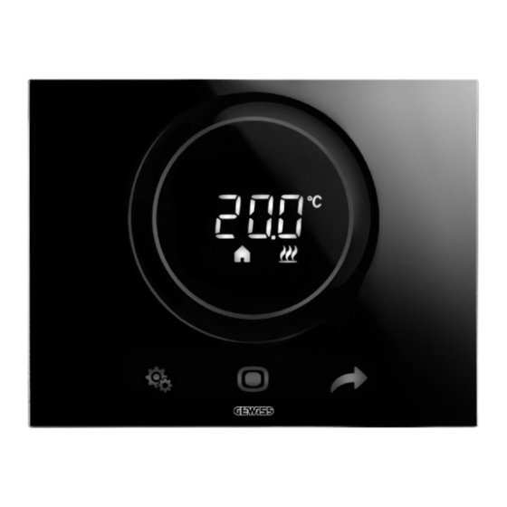
DESCRIZIONE GENERALE Elementi di comando e visualizzazione Descrizione comandi COMANDI TOUCH RETROILLUMINATI Tasto SET: ingresso modalità impostazione parametri Tasto MODE: selezione modalità di funzionamento o conferma valori Selezione delle pagine (in funzionamento normale) o dei parametri (in modalità impostazione parametri) SLIDER CIRCOLARE TOUCH RETROILLUMINATO Slider a scorrimento circolare per la selezione del valore da assegnare al parametro selezionato. -
Page 7: Istruzioni D'installazione
ISTRUZIONI D’INSTALLAZIONE Corretto posizionamento Per la corretta rilevazione della temperatura dell’ambiente controllare, il termostato non deve essere installato in nicchie, vicino a porte finestre, accanto termosifoni o condizionatori e non deve essere colpito da correnti d’aria e dall’illuminazione solare diretta. Montaggio Il montaggio del termostato può... -
Page 8: Connessioni Elettriche
ISTRUZIONI D’INSTALLAZIONE Aggancio Sgancio Connessioni elettriche La figura B mostra lo schema delle connessioni elettriche. Collegare l'alimentazione, gli eventuali ingressi e il contatto d'uscita ai morsetti a vite posti sul retro del termostato (figura A). -
Page 9: Istruzioni D'impiego
ISTRUZIONI D’IMPIEGO Comportamento alla caduta ed al ripristino dell’alimentazione Alla caduta dell’alimentazione il dispositivo non compie nessuna azione. Al ripristino dell'alimentazione, il termostato riattiva le condizioni precedenti la caduta. Il termostato è dotato di un sistema di accumulo energia per il mantenimento dell'orario in caso di mancanza di alimentazione (max 1h). -
Page 10: Dati Tecnici
DATI TECNICI Alimentazione 12-24Vac/dc Assorbimento alimentazione max. 500mA Elementi di comando 3 comandi touch 1 slider circolare touch Ingressi 1 ingresso per contatto privo di potenziale per contatto finestra (lunghezza cavi max. 10m) 1 ingresso per sensore temperatura esterna (es: GW 10 800) (tipo NTC 10K) Uscite 1 relè... - Page 11 CONTENTS page GENERAL WARNINGS Pack contents ............12 GENERAL DESCRIPTION Briefly .
-
Page 12: General Warnings
IEC 60364, or the European harmonization document HD 60364. Gewiss sales organization is ready to provide full explanations and technical data on request. Pack contents n. -
Page 13: General Description
GENERAL DESCRIPTION Briefly The ICE thermostat manages the temperature of the room where it is installed. The temperature is regulated by commanding the heating/cooling solenoid valve via the local relay. The device can manage two-way (common logic) heating/cooling systems as it has a single output relay. The setpoint values used by the thermostat are stored in the device, and can be modified via the local menu. -
Page 14: Command And Display Elements
GENERAL DESCRIPTION Command and display elements Description of the commands BACKLIT TOUCH COMMANDS SET button key: parameter setting mode input MODE button key: operating mode selection or value confirmation Selection of pages (in normal operation) or parameters (in parameter setting mode) BACKLIT CIRCULAR TOUCH SLIDER A circular sliding slider for selecting the value to assign to the selected parameter. -
Page 15: Installation Instructions
INSTALLATION INSTRUCTIONS Correct positioning To correctly measure the controlled ambient temperature, the thermo- stat must not be installed in niches, near doors or windows, or next to ra- diators or air-conditioning units, and it must not be in the line of draughts or direct sunlight. -
Page 16: Electric Connections
INSTALLATION INSTRUCTIONS Coupling Release Electric connections Figure B shows a diagram of the electrical connections. Connect the power supply, and connect any inputs and the output contact to the screw terminals on the back of the thermostat (figure A). -
Page 17: User Instructions
USER INSTRUCTIONS Behaviour upon the failure and resetting of the power supply If there is a power failure, the device will not implement any action. When the power supply is restored, the thermostat will reactivate the conditions that were in place beforehand. The thermostat is equipped with an energy accumulation system to maintain the time in the event of a power failure (max 1h). -
Page 18: Technical Data
TECHNICAL DATA Power supply 12-24V AC/DC Power supply absorption max. 500mA Command elements 3 touch commands 1 circular touch slider Inputs 1 input for potential-free contact for window contact max. cable length 10m) 1 input for external temperature sensor (e.g. GW 10 800) (NTC 10K type) Outputs 1 relay with NO/NC potential-free contact... - Page 19 SOMMAIRE page CONSIGNES GÉNÉRALES Contenu de la confection ..........20 DESCRIPTION GÉNÉRALE En synthèse .
-
Page 20: Consignes Générales
électriques à basse tension CEI 60364, ou le document d'harmonisation européen HD 60364. Le réseau de vente de Gewiss est prêt à fournir des explications complètes et des données techniques sur demande. Contenu de la confection n. -
Page 21: Description Générale
DESCRIPTION GÉNÉRALE En synthèse Le thermostat ICE permet de gérer la température de l'ambiance dans laquelle il est installé.La régulation de la température est exécutée en commandant l'électrovanne de chauffage et de climatisation à travers le relais local.Le dispositif est en mesure de gérer des installations de chauffage et de climatisation à... -
Page 22: Éléments De Commande Et De Visualisation
DESCRIPTION GÉNÉRALE Éléments de commande et de visualisation Description des commandes COMMANDES TACTILES RÉTRO-ÉCLAIRÉES Touche SET : entrée dans la modalité de configuration des paramètres Touche MODE : sélection de la modalité de fonctionnement ou de confirmation des valeurs Sélection des pages (en fonctionnement courant) ou des paramètres (en modalité de configuration des paramètres) CURSEUR CIRCULAIRE TACTILE RÉTRO-ÉCLAIRÉ... -
Page 23: Consignes D'installation
CONSIGNES D'INSTALLATION Positionnement correct Pour le relevé de la température de l’ambiance à contrôler, le thermostat ne doit pas être installé dans des niches, près dune porte ou d'une fenêtre, près d'un radiateur ou d'un climatiseur et il ne doit pas se trouver dans un courant d'air ou à... -
Page 24: Connexions Électriques
CONSIGNES D'INSTALLATION Accrochage Décrochage Connexions électriques La figure B reporte le schéma des connexions électriques. Raccorder l'alimentation, les éventuelles entrées et le contact de sortie aux bornes à vis montées sur l'arrière du thermostat (figure A). -
Page 25: Consignes D'utilisation
CONSIGNES D'UTILISATION Comportement à la coupure et au rétablissement de l'alimentation À la coupure de l'alimentation, le dispositif n'exécute aucune action. Au rétablissement de l'alimentation, le thermostat réactive les conditions ayant précédé la coupure. Le thermostat est équipé d'un système d'accumulation d'énergie pour le maintien de l'horaire en cas de coupure de l'alimentation (max 1h) Après une coupure et le réarmement successif de l'alimentation, le contact du relais à... -
Page 26: Données Techniques
DONNÉES TECHNIQUES Alimentation 12-24Vca/cc Absorption de l'alimentation max 500mA Éléments de commande 3 commandes tactiles 1 curseur circulaire tactile Entrées 1 entrée libre de potentiel pour le contact de la fenêtre (longueur max des câbles 10m) 1 entrée du capteur de température extérieure (par exemple : GW 10 800) (type NTC 10K) Sorties... - Page 27 ÍNDICE pág ADVERTENCIAS GENERALES Contenido del embalaje ..........28 DESCRIPCIÓN GENERAL En síntesis .
-
Page 28: Advertencias Generales
CEI 60364 o a la norma europea armonizada HD 60364. La organización de ventas de Gewiss está a disposición para proporcionar aclaraciones y datos técnicos si se solicitan. Contenido del embalaje n. -
Page 29: Descripción General
DESCRIPCIÓN GENERAL En síntesis El termostato ICE permite gestionar la temperatura del ambiente donde está instalado. La regulación de la temperatura se efectúa accionando, a través del relé local, la electroválvula de calefacción/refrigeración. El dispositivo puede gestionar las instalaciones de calefacción/refrigeración de dos vías (lógica común), estando dotado de un solo relé... -
Page 30: Elementos De Mando Y Visualización
DESCRIPCIÓN GENERAL Elementos de mando y visualización Descripción mandos MANDOS TÁCTILES RETROILUMINADOS Tecla SET: entrada en modo de configuración de parámetros Tecla MODE: selección del modo de funcionamiento o confirmación de valores Selección de las páginas (en funcionamiento normal) o de los parámetros (en modo de configuración de parámetros) SLIDER CIRCULAR TÁCTIL RETROILUMINADO Slider deslizante circular para la selección del valor que se debe asignar al parámetro seleccionado. -
Page 31: Instrucciones De Instalación
INSTRUCCIONES DE INSTALACIÓN Colocación correcta Para la detección correcta de la tem- peratura del ambiente que se debe controlar, el termostato no debe estar instalado en nichos, cerca de puertas o ventanas, al lado de ter- mosifones o aires acondicionados y no debe recibir corrientes de aire ni la iluminación directa del sol. -
Page 32: Conexiones Eléctricas
INSTRUCCIONES DE INSTALACIÓN Enganche Desenganche Conexiones eléctricas La figura B muestra el esquema de conexiones eléctricas. Conectar la alimentación, las entradas que hubiera y el contacto de salida a los bornes de tornillo situados en la parte posterior del termostato (figura A). -
Page 33: Instrucciones De Uso
INSTRUCCIONES DE USO Comportamiento en la caída y en el restablecimiento de la alimentación En la caída de alimentación, el dispositivo no realiza ninguna acción. Cuando se restablece la alimentación, el termostato reactiva las condiciones anteriores a la caída. El termostato está dotado de un sistema de acumulación de energía para el mantenimiento del horario en caso de falta de alimentación (máx. -
Page 34: Datos Técnicos
DATOS TÉCNICOS Alimentación 12-24Vca/cc Absorción de la alimentación máx. 500mA Elementos de mando 3 mandos táctiles 1 slider circular táctil Entradas 1 entrada para contacto sin potencial para contacto de ventana (longitud de cables máx. 10m) 1 entrada para sensor de temperatura externa (ej.: GW 10 800) (tipo NTC 10K) Salidas... - Page 35 INHALT ALLGEMEINE HINWEISE Packungsinhalt ............36 ALLGEMEINE BESCHREIBUNG Ñ...
-
Page 36: Allgemeine Hinweise
Norm für Niederspannungsanlagen IEC 60364 oder den Europäischen Harmonisierungsdokument HD 60364 beachten. Für genauere Informationen und technische Daten wenden Sie sich bitte an den Vertrieb von Gewiss. Packungsinhalt 1 Stück ICE Thermostat für Unterputzmontage (einschließlich Abdeckrahmen und... -
Page 37: Allgemeine Beschreibung
ALLGEMEINE BESCHREIBUNG Kurzbeschreibung Das ICE-Thermostat gestattet die Temperaturverwaltung im Raum, in dem es installiert ist. Die Temperaturregelung erfolgt durch Steuerung des Magnetventils der Heizung/Kühlung über ein lokales Relais.Das Gerät kann 2-Rohr-Heiz-/-Kühlanlagen (gemeinsame Logik) steuern, da es nur über ein Ausgangsrelais verfügt. Die vom Thermostat benutzten Sollwerte werden im Gerät gespeichert und können über das lokale Menü... -
Page 38: Elemente Für Steuerung Und Ansicht
ALLGEMEINE BESCHREIBUNG Elemente für Steuerung und Ansicht Beschreibung der Steuerungen HINTERGRUNDBELEUCHTETE BERÜHRUNGSSENSIBLE BEDIENELEMENTE SET-Taste: Eingang Parameter-Einstellungsmodus MODE-Taste: Auswahl der Betriebsart oder Bestätigung der Werte Auswahl der Seiten (bei Normalbetrieb) oder der Parameter (im Parameter-Einstellungsmodus) HINTERGRUNDBELEUCHTETER RUNDER BERÜHRUNGSSENSIBLER SCHIEBER Runder Schieber zum Auswählen des Wertes, der dem ausgewählten Parameter zugeordnet werden soll. Die runde Lichtführung, die den Gleitbereich beleuchtet, nimmt während der Aktivierungsphase der Heizung/Kühlung oder je nach ausgeübter Funktion des gerade in Änderung befindlichen Parameters eine unterschiedliche Farbe an (rot für die Heizung und blau für die Kühlung) -
Page 39: Installationsanweisungen
INSTALLATIONSANWEISUNGEN Korrekte Positionierung Für die korrekte Erhebung der Tem- peratur des zu kontrollierenden Raums darf der Thermostat nicht in Nischen, in der Nähe von Türen oder Fenstern oder neben Heizkörpern oder Klimageräten installiert werden und es darf keinen Luftströmen oder direkter Sonnenbestrahlung ausge- setzt werden. -
Page 40: Elektrische Anschlüsse
INSTALLATIONSANWEISUNGEN Einrastbefestigung Ausklinken Elektrische Anschlüsse Die Abbildung B zeigt den elektrischen Anschlussplan. Die Versorgung, die eventuellen Eingänge und den Ausgangskontakt an die Schraubklemmen auf der Rückseite des Thermostats anschließen (Abbildung A). -
Page 41: Gebrauchsanweisung
GEBRAUCHSANWEISUNG Verhalten bei Ausfall und Rücksetzung der Versorgung Bei Ausfall der Versorgung führt das Gerät keine Aktion aus. Bei der Wiederherstellung der Versorgung stellt der Thermostat die Bedingungen vor dem Ausfall wieder her. Der Thermostat ist mit einem Energiespeichersystem zur Beibehaltung der Uhrzeit bei Stromausfall (max 1h) ausgestattet. -
Page 42: Technische Daten
TECHNISCHE DATEN Spannungsversorgung 12-24VAC/DC Stromaufnahme der Stromversorgung max. 500mA Bedienelemente 3 berührungssensible Bedienelemente 1 runder berührungssensibler Schieber Eingänge 1 Eingang für potentialfreien Kontakt für Fensterkontakt (max. Kabellänge 10m) 1 Eingang für Außentemperatursensor (z.B. GW 10 800) (Typ NTC 10K) Ausgänge 1 Relais mit potentialfreiem Schließer/Öffner-Kontakt Max. - Page 44 According to article 9 paragraph 2 of the European Directive 2004/108/EC, the responsible for placing the apparatus on the Community market is: GEWISS S.p.A Via A. Volta, 1 - 24069 Cenate Sotto (BG) Italy Tel: +39 035 946 111 Fax: +39 035 945 270 E-mail: qualitymarks@gewiss.com +39 035 946 111 sat@gewiss.com...
Need help?
Do you have a question about the GW 16 971CB and is the answer not in the manual?
Questions and answers