
Related Manuals for Emerson Liebert 610 Series


Summary of Contents for Emerson Liebert 610 Series
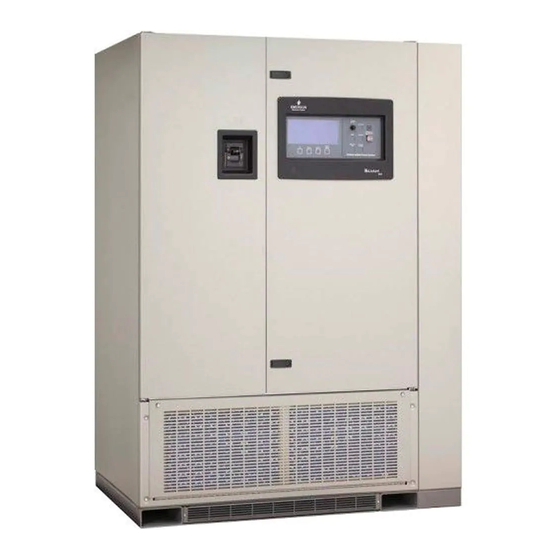
- Page 1 DISCONTINUED AC Power PRODUCT For Business-Critical Continuity™ Liebert Series 610 ® ™ Operation & Maintenance Manual - 100-1000kVA, 60Hz, Three Phase Multi-Module DISCONTINUED PRODUCT...
-
Page 2: Contacting Liebert For Support
ATTERY ABINET RECAUTIONS The following warning applies to all battery cabinets supplied with UPS systems. Additional warn- ings and cautions applicable to battery cabinets may be found in Important Safety Instructions and 4.4 - Battery Maintenance. WARNING Internal battery strapping must be verified by manufacturer prior to moving a battery cabinet (after initial installation). -
Page 3: Table Of Contents
TABLE OF CONTENTS ....... . . I ATTERY ABINET RECAUTIONS NSIDE RONT OVER... - Page 4 Modes of Operation............73 3.3.1 Load on Bypass .
- Page 5 FIGURES Figure 1 Multi-Module UPS, 100-500kVA ........... . 2 Figure 2 Multi-Module UPS, 500-750kVA .
- Page 6 Figure 50 Battery equalize screen ............62 Figure 51 SCC status and alarm message areas .
-
Page 7: Important Safety Instructions
MPORTANT AFETY NSTRUCTIONS SAVE THESE INSTRUCTIONS This manual contains important instructions that should be followed during installation and mainte- nance of your Liebert Series 610 UPS and batteries. WARNING Exercise extreme care when handling UPS cabinets to avoid equipment damage or injury to personnel. -
Page 8: Introduction
Introduction NTRODUCTION System Description The role of the parallel-redundant multi-module UPS system is to supply uninterruptible, clean power to the critical load. The UPS maintains a full-voltage, low-distortion output, even if the utility source power sags, becomes distorted or fails. If there is an outage of the source power, the UPS maintains power to the load until an alternate source of power is activated or until the original power source is restored. -
Page 9: Figure 2 Multi-Module Ups, 500-750Kva
Introduction In the unlikely event of a fault within the UPS, the SCC control logic, which continuously monitors all critical circuits within the UPS system, transfers the load to bypass without interruption and simul- taneously activates local and remote alarms. If a fault is detected in an individual UPS module, that module is automatically disconnected from the critical bus and shut down. -
Page 10: Reliability
Introduction Figure 3 System Control Cabinets Types of System Control Cabinets (SCCs) • SCCT—A stand-alone cabinet containing system control logic for up to six UPS modules, a static bypass switch, manually operated disconnects for the static bypass switch and two motor-oper- ated system circuit breakers. -
Page 11: Safety Precautions
Introduction Other Factors to Consider Reliability depends on more than just UPS module design. Improper installation can cause any sys- tem to fail. To prevent this, customer engineers from Liebert Global Services thoroughly inspect the installation of all our systems to ensure they are installed properly and operating within performance specifications. -
Page 12: Recharge
Introduction 1.4.3 Recharge After the utility source power is restored or an alternate power source becomes available, each recti- fier/charger slowly walks-in to once again power the inverters and recharge the battery plant. 1.4.4 Overload Overloads in critical systems may be caused by inrush currents during connected equipment start-up or by faults in the critical load or distribution network. -
Page 13: Figure 4 Scc Controls And Display Screen With Example Of The Monitor/Mimic Screen
Introduction Figure 4 SCC controls and display screen with example of the Monitor/Mimic screen © 1989-2003 DISCONTINUED PRODUCT... -
Page 14: Options
Introduction The operator controls and Monitor/Mimic screen for the System Control Cabinet (SCC) are shown in Figure 4. The controls and display screen for each UPS module are shown in Figure 5. Each cabinet (SCC or module) has the displays and controls required to monitor and perform its functions. Figure 4 shows a three-module system designed for redundant operation. - Page 15 Introduction 2. Battery Racks or Cabinets The battery racks are specifically designed for stationary service batteries. They are painted with electrolyte-resistant paint for corrosion resistance. Battery cabinets are available for 150 through 600kVA modules. 3. Module Battery Disconnect The UPS system utilizes a separate Module Battery Disconnect for remotely located batteries. A sensing circuit in the UPS module, set at the battery low voltage limit, trips the Module Battery Disconnect to safeguard the battery from excessive discharge.
-
Page 16: Theory Of Operation
Theory of Operation HEORY OF PERATION General Component Descriptions The UPS system includes all of the equipment necessary to continuously provide computer-grade AC power to a critical load, even when there is an interruption of the utility power. It consists of a System Control Cabinet (SCC), UPS modules and a back-up battery plant. -
Page 17: Ups Module
Theory of Operation Figure 6 UPS module block diagram MULTI-MODULE UPS SYSTEM Control Wiring To SCC CONTROL POWER Controls Utility Output Rectifier/ Input Inverter Power Charger Output Power Input To SCC Battery CB - Circuit Breaker MBD - Module Battery Disconnect SCC - System Control Cabinet 2.1.2 UPS Module... -
Page 18: Detailed Component Descriptions
Theory of Operation Detailed Component Descriptions 2.2.1 Controls Hardware The Liebert Series 610 UPS Operator Interface Display System is designed to provide all of the infor- mation that is required for the operation of each UPS cabinet (the System Control Cabinet and each module). -
Page 19: Rectifier/Charger
Theory of Operation 2.2.2 Rectifier/Charger The UPS module rectifier/charger consists of an input circuit breaker, AC current limiting circuit, battery equalize charge circuit, DC filter, battery charge current limiting circuit and bridge rectifiers. Optional items are an isolation transformer and a 12-pulse rectifier (these are standard on 1000kVA units). -
Page 20: Battery Charging Circuit
Theory of Operation 2.2.3 Battery Charging Circuit The UPS module charging circuit is capable of recharging the battery plant to 95% of full capacity within 10 times the discharge time. Recharging the last 5% takes longer because of characteristics inherent in the battery. DC ripple voltage is limited to less than 0.5% RMS to preserve battery life during long-term float charging while the UPS system is operating on utility source power. -
Page 21: Inverter
Theory of Operation 2.2.4 Inverter The inverter is a solid state device that converts the DC output of the rectifier/charger or the battery to AC power. Operation The inverter converts DC power—from either the battery or the rectifier/charger—into three pulse- width-modulated/six-step waveforms. -
Page 22: Static Bypass
Theory of Operation 2.2.5 Static Bypass A static bypass is an integral part of the UPS System Control Cabinet (SCC). Refer to Figure 7. The static bypass consists of two reverse-paralleled SCRs (silicon-controlled rectifiers) per phase and solid-state switching devices working in conjunction with the motor-operated System Bypass Breaker (SBB). - Page 23 Theory of Operation Static Switch Isolation The motor-operated system bypass circuit breaker (SBB), wired in parallel with the static switch, automatically closes in approximately 200 milliseconds after the load is transferred to the bypass power source, removing the static switch from the power flow. Also, if required for maintenance, the static switch can be isolated from the bypass line by opening (to the OFF position) the Static Switch Disconnects.
- Page 24 Theory of Operation Transfer and Retransfer Conditions 1. Automatic Transfers to Bypass Critical bus conditions that will initiate an automatic transfer of the critical load from the UPS system to the bypass source are: a. System Overload: overcurrent condition in excess of the overload rating of the System Control Cabinet (SCC).
-
Page 25: Redundant Mode
Theory of Operation 6. Retransfer Inhibited A retransfer from the bypass source to the UPS system shall be inhibited if any of the following conditions exist: a. Manual (and Automatic) Retransfer Inhibitions: 1. UPS system-to-bypass voltage difference (ΔV) exceeds a predetermined percentage (normally 5%). -
Page 26: Operation
Operation PERATION Display Screen and Operator Controls Each Liebert Series 610 UPS cabinet is equipped with a microprocessor-based Operator Control Panel and Display Screen and System Control Panel designed for convenient and reliable operation. The System Control Cabinet (SCC) performs different functions than the UPS modules. Each cabinet has the controls and displays required to operate and monitor its functions. -
Page 27: Figure 8 Typical Operator Controls
Operation Figure 8 Typical operator controls 100kVA- 500kVA 1000kVA Table 1 Typical operator controls Item Description Function This manually operated circuit breaker provides power to the UPS module rectifier. In Input Circuit Breaker (CB1) 625-750kVA modules and some 500kVA modules, this breaker is located in the transformer cabinet. -
Page 28: Figure 9 Operator Controls, Typical Scct System Control Cabinet
Operation Figure 9 Operator controls, typical SCCT System Control Cabinet Table 2 Typical SCCT System Control Cabinet operator controls Item Description Function UPS Output Circuit This motorized circuit breaker connects the critical load to the UPS system Breaker output. System Bypass Circuit This motorized circuit breaker connects the critical load to the bypass line. -
Page 29: Figure 10 Liebert Series 610 Ups And Scc Operator Control Panels
Operation Figure 10 Liebert Series 610 UPS and SCC operator control panels Numbers are used as keys to data in Table 3, below. Table 3 Liebert Series 610 UPS and SCC operator control panels Item Description (Location) Function Display Screen This screen displays all vital UPS information in one convenient location. -
Page 30: Figure 11 Switches Behind Scc Control Panel Door
Operation Figure 11 Switches behind SCC control panel door Numbers are used as keys to data in Table 4, below. Table 4 Liebert Series 610 UPS and SCC operator control panels Item Description (Location) Function Press this button to make authorized changes to any site parameter protected Interlock Button by the Security Access function. -
Page 31: Menu Tree Navigation
Operation Menu Tree Navigation The Operator Interface Display is a blue-background display with white text. The display is always on, but the backlight will remain lit for 15 minutes following any display activation. After 15 minutes, the backlight will go out and the display may appear very dim. To reactivate the backlight, push any key. -
Page 32: Master Menu Screen
Operation Figure 12 illustrates the primary screens that you can access through the Operator Interface Display System. The liquid crystal display (LCD) screen provides a full 80 characters by 25 lines of informa- tion for easy readability. The following sections describe what these screens display and how and when to use them. - Page 33 Operation From any primary screen (accessed directly from the Master Menu), pushing the Select pad once will return you to the Master Menu. From any secondary screen, pushing the Select pad twice will return you to the Master Menu. Please note that some screens have multiple pages. However, in each case, instructions appear for accessing other pages.
-
Page 34: Scc Monitor/Mimic Display Screen
Operation • Battery Test (MMU Only)—The optional battery test screen allows the operator to perform manual battery tests to determine the general condition of the battery system. The results of the last 10 tests are recorded in non-volatile storage and can be retrieved through the battery test results screen. - Page 35 Operation Status/Alarm Message Areas The status/alarm message areas display vital information about the operation of the UPS system. During normal operation no alarm messages should be present. Changes in the status of the system and possible alarm conditions can be monitored. Both the status and the alarm messages are dis- played in reverse video (highlighted—light on dark).
-
Page 36: Module Monitor/Mimic Display Screen
Operation 3.2.3 Module Monitor/Mimic Display Screen From module Master Menu move the highlighted cursor to MONITOR/MIMIC DISPLAY. Press the Select pad and the Monitor/Mimic screen is displayed. The Monitor/Mimic display screen is a simplified block diagram of the UPS module and power connec- tions. - Page 37 Operation Alarm Messages The alarm message area displays vital information about the operation of the UPS system. During normal operation no alarm messages should be present. Alarm conditions can be monitored. The alarm messages are displayed in reverse video (highlighted— light on dark). To clear a latching alarm, you must also press the Alarm Reset pad after the alarm condition is corrected.
-
Page 38: Figure 16 Monitor/Mimic Display Example: Normal Power Flow
Operation Figure 16 Monitor/Mimic display example: Normal power flow © 1989-2003 BYPASS INPUT LOAD 627 KVA / 502 KW 480V 480V 480V 60.0 Hz UPS RATINGS 755A 755A 755A SCCB 1600 UPS INPUT PWR 3 OF 3 MODULES OUTPUT VOLTAGE CONNECTED 480V 480V... -
Page 39: Figure 17 Monitor/Mimic Display Example: Utility Fail
Operation Figure 17 Monitor/Mimic display example: Utility fail © 1989-2003 LOAD BYPASS INPUT 627 KVA / 502 KW 0 Hz UPS RATINGS 755A 755A 755A SCCB 1600 UPS INPUT PWR 3 OF 3 MODULES CONNECTED OUTPUT VOLTAGE REDUNDANT 480V 480V 480V 60.0Hz MOD 1 ON LINE SUM ALM Byp Not Avail... -
Page 40: Figure 18 Monitor/Mimic Display Example: Load On Bypass, Ups Modules On And Charging Battery
Operation Figure 18 Monitor/Mimic display example: Load on bypass, UPS modules on and charging battery © 1989-2003 BYPASS INPUT LOAD 627 KVA / 502 KW 480V 480V 480V 60.0 Hz UPS RATINGS 755A 755A 755A SCCB 1600 UPS INPUT PWR 3 OF 3 MODULES CONNECTED OUTPUT VOLTAGE... -
Page 41: Figure 19 Monitor/Mimic Display Example: Load On Ups, One Ups Module Off Line
Operation Figure 19 Monitor/Mimic display example: Load on UPS, one UPS module off line © 1989-2003 LOAD LOAD BYPASS INPUT 627 KVA / 502 KW 0 KVA / 0 KW 480V 480V 480V 60.0 Hz UPS RATINGS UPS RATINGS 755A 755A 755A AP658-71... -
Page 42: Figure 20 Monitor/Mimic Display Example: Load On Bypass, All Ups Modules Off Line
Operation Figure 20 Monitor/Mimic Display example: Load on bypass, all UPS modules off line © 1989-2003 LOAD LOAD BYPASS INPUT 627 KVA / 502 KW 0 KVA / 0 KW 480V 480V 480V 60.0 Hz UPS RATINGS UPS RATINGS 755A 755A 755A AP658-71... -
Page 43: Walk-In Display Screen
Operation 3.2.4 Walk-In Display Screen From the module Master Menu, highlight WALK-IN DISPLAY and then press the Select pad. Note that this screen is displayed at the UPS modules but is not required at the System Control Cabinet (SCC). Figure 21 Walk-in display screen during start-up SELECT : DOWN : MASTER MENU... -
Page 44: Status Reports Screens
Operation 3.2.5 Status Reports Screens Go to the Master Menu and move the highlighted cursor to STATUS REPORTS. Press the Select button and the Status Reports screen is displayed. The Status Report screen is divided into four submenu reports: PRESENT STATUS, EVENT HIS- TORY, HISTORY STATUS and SYSTEM STATUS. -
Page 45: Figure 23 Present Status Report Screens, Scc (Above) And Module
Operation Figure 23 Present status report screens, SCC (above) and module PRESENT STATUS MODULE-0 01/12/98 14:06:26 FRAME 35 ORDER - 000000 SITE ID - 00000 SITE TAG - 0000000 **** ACTIVE ALARMS **** Batt Discharging HERTZ LOAD TIME OUTPUT VOLTS OUTPUT AMPS OUTPUT FREQUENCY 60.0... -
Page 46: Figure 25 History Status Report Screens
Operation History Status The History Status screen displays 64 frames, of 4 milliseconds each, from the Present Status screen. Note that the values for output volts and amps are updated once each millisecond. Alarms are listed in the sequence they occurred, within 1 millisecond resolution. The frames are stored in a buffer (a computer information storage technique). - Page 47 Operation Table 5 shows the alarm conditions that stop the History Status buffer from gathering data. Table 5 Alarm conditions that freeze history data gathering Alarm in SCC Alarm in Module Auto Transfer to Bypass DC Cap Fuse Blown Output Overvoltage DC Overvoltage Shutdown Output undervoltage Inverter Fault...
-
Page 48: Figure 26 Battery Cycle Monitor Screen
Operation System Status The System Status screen displays the module Total Operating Hours, Enable Backlight and the Bat- tery Cycle Monitor. Battery Cycle Monitor—Module Only Selecting the Battery Cycle Monitor gives you access to detailed information about the module’s most recent battery discharge events. -
Page 49: Figure 27 Battery Cycle Monitoring Summary Screen
Operation The Summary screen (Figure 27) shows Total Number of Discharge Cycles, Accumulated Battery Time, Accumulated Battery Amp Hours, Accumulated Battery Kilowatt Hours and Battery Tempera- ture. During a battery discharge event, the screen changes to show information about the present dis- charge cycle. -
Page 50: System Configuration Screens
Operation 3.2.6 System Configuration Screens Go to the Master Menu and move the highlighted cursor to SYSTEM CONFIGURATION. Press the Select pad and the System Configuration screen is displayed. The System Configuration screen lists parameters that can be changed to adjust your UPS modules and the SCC to your site requirements. -
Page 51: Figure 30 Date Screen
Operation Date This is the system’s real-time date setting. The system control program sends to each module the date entered at the System Control Cabinet (SCC). You cannot change the system date from the control panel of a UPS module. Figure 30 Date screen ©... -
Page 52: Figure 31 Time Screen
Operation Time This is the system’s real-time clock. The system control program sends to each module the time entered at the System Control Cabinet (SCC). You cannot change the system time from the control panel of a UPS module. Figure 31 Time screen ©... -
Page 53: Figure 32 Auto Dial Setting Screen
Operation Auto Dial This is a feature that automatically dials (through a customer supplied PC-compatible modem) a pre- programmed telephone number (up to 12 digits) when specified alarm conditions occur within the UPS system. The connection for the modem is at the SCC. Automatic dial attempts to the first num- ber are made at periodic intervals for 30 minutes. -
Page 54: Figure 33 Modem Baud Rate
Operation Modem Baud Rate This sets the transmission rate at which the system relays data to a terminal through the modem. Figure 33 Modem baud rate UP: CURSOR UP DOWN: CURSOR SELECT: CHOOSE AUTO DIAL SETTING SCREEN EXIT Enable Auto Dial ............. YES Enable Communication Check........ -
Page 55: Figure 35 Scc System Options Screen
Operation To change the Maximum Auto-Retransfer Attempts parameter, do the following at the SCC: 1. From the System Configuration Screen, press the Up or Down pad to highlight Maximum Auto- Retransfer Attempts. 2. Press the Select pad. The screen above will appear. 3. -
Page 56: Figure 37 Battery Test Screen-Mmu Only
Operation Figure 37 Battery test screen—MMU only UP: CURSOR UP DOWN: CURSOR DOWN SELECT: CHOOSE BATTERY TEST EXIT Battery Test Results Start Battery Test Stop Battery Test Select Battery Type..........15 min Figure 38 Battery test results screen UP: CURSOR UP DOWN: CURSOR DOWN SELECT: CHOOSE End DC... -
Page 57: Figure 39 Monitor/Mimic Display Example: Continuous Duty Static Switch
Operation Figure 39 Monitor/Mimic display example: Continuous Duty Static Switch LOAD BYPASS INPUT 627 KVA / 502 KW ∅A-B ∅B-C ∅C-A 480V 480V 480V ∅A ∅B ∅C CDSS 60.0Hz 755V 755V 755V UPS RATINGS 3 OF 3 MODULES SCCB 1600 CONNECTED UPS INPUT PWR OUTPUT VOLTAGE... -
Page 58: Alarm Limit Settings Screen
Operation 3.2.7 Alarm Limit Settings Screen Go to the Master Menu and move the highlighted cursor to LIMIT SETTINGS. Press the Select pad and the Limit Settings screen is displayed. The Alarm Limit Settings screen has Security Access to enable an authorized Liebert field-service engineer to adjust the UPS system alarm limit settings. - Page 59 Operation Battery Rating (Modules Only): This setting is a battery discharge rating in kilowatts under par- tial load for an extended period, typically 60 minutes. The UPS uses the two battery shutdown voltage settings and the two battery discharge ratings in computing rated and calculated time remaining dur- ing a discharge event.
-
Page 60: Load Transfer Procedures Screen
Operation 3.2.8 Load Transfer Procedures Screen Go to the SCC Master Menu and move the highlighted cursor to LOAD TRANSFER PROCE- DURES. Note that this screen is displayed at the System Control Cabinet but is not required at the UPS modules. Press the Select pad and the Load Transfer Procedures screen is displayed. The Load Transfer Procedures screen contains instructions to transfer the critical load between the UPS system and the bypass line. -
Page 61: Start-Up Procedures Screen
Operation 3.2.9 Start-Up Procedures Screen From the SCC Master Menu, move the highlighted cursor to START-UP PROCEDURES. Press the Select pad and the SCC Start-Up Procedures screen is displayed (Figure 42). This screen contains the steps you must follow to start-up the UPS system. The instructions are listed so you can review them prior to performing the start-up. -
Page 62: 3.2.10 Shutdown Procedures Screen
Operation Figure 43 Module start- up procedures screens DOWN : NEXT PAGE SELECT : MASTER MENU © 1989-2003 START-UP PROCEDURES Verify that the control power is applied to the system control cabinet (check the display on the system control cabinet). Wait approximately two (2) minutes before attempting any other action . -
Page 63: Figure 44 Scc Shutdown Procedures Screen
Operation Figure 44 SCC shutdown procedures screen © 1989-2003 SHUTDOWN PROCEDURES If load is not already being supplied by the bypass line, select the "LOAD TRANSFER PROCEDURE" screen and follow the instructions to transfer the load to bypass. Go to the modules(s) and follow the module "SHUTDOWN PROCEDURES." Press the ALARM RESET button to clear alarms which are no longer active. -
Page 64: Battery Time Screen (Module Only)
Operation To perform the shutdown procedure, transfer the critical load from the UPS system to the bypass line (at the SCC). Then trip open the UPS module output and battery circuit breaker (MBD) and manually open the UPS module input circuit breaker. The Control Power switch may be turned Off if required for maintenance procedures. -
Page 65: Figure 47 Battery Time Screen (45-Minute Discharge)
Operation Values for Calculated Total Time and Calculated Time Remaining will appear on the screen approxi- mately two minutes after the beginning of the discharge event. Calculated Time Remaining also appears on the Present Status Report screen. Both Calculated Total Time and Calculated Time Remaining will be updated every six seconds, reflecting actual load changes and battery condition. - Page 66 Operation The Liebert Series 610 dynamically adjusts the Battery Shutdown voltage based on battery charac- teristics and the length of the current discharge event. If a discharge event extends past 15 minutes (i.e., the load is less than the full design rating), the Battery Shutdown voltage setting is gradually and automatically increased, to protect the batteries from deep discharge.
-
Page 67: 3.2.12 Meter Calibration Screen
Operation 3.2.12 Meter Calibration Screen Go to the Master Menu and move the highlighted cursor to METER CALIBRATION. Press the Select pad and the Meter Calibration screen is displayed. The Meter Calibration screen enables a Liebert field-service engineer to adjust the calibration of the UPS metered functions at each cabinet. -
Page 68: 3.2.13 Battery Equalize Screen
Operation 3.2.13 Battery Equalize Screen Go to the Master Menu and move the highlighted cursor to BATTERY EQUALIZE. Press the Select pad and the Battery Equalize screen is displayed. The Battery Equalize screen enables the operator to adjust the battery equalize time. It is also used to choose between auto and manual battery equalize recharging modes. -
Page 69: 3.2.14 Alarm And Status Messages
Operation 3.2.14 Alarm and Status Messages Module Status Messages The module status messages indicate how many UPS modules are included in the system and the present status of each module. The following status messages may appear in the module status area. 1. -
Page 70: Table 8 Abbreviations Used In Alarm Messages
Operation Load Block Messages Status messages in the Load Block indicate how many modules are in the system, how many modules are ON LINE and whether the system is operating in the redundant mode. The following status messages may appear in the load block. 1. -
Page 71: Table 9 Alarm Messages - Meaning And Corrective Action
Operation Table 9 Alarm messages - meaning and corrective action Alarm Cabinet Special Message Location Functions Meaning and Corrective Action AC INPUT The rectifier input line voltage is outside of specified limits or the input circuit breaker is opened while the battery circuit breaker remains closed. Input Fail —... - Page 72 Operation Table 9 Alarm messages - meaning and corrective action (continued) Alarm Cabinet Special Message Location Functions Meaning and Corrective Action BYPASS (Cont’d.) The critical load has been automatically transferred to the bypass line. Auto Transfer to Use the History Status screen to determine the cause for the transfer. D, E, F Bypass Clear all of the alarms before attempting to retransfer the load from...
- Page 73 Operation Table 9 Alarm messages - meaning and corrective action (continued) Alarm Cabinet Special Message Location Functions Meaning and Corrective Action UPS SYSTEM (Cont’d.) The load on the UPS has exceeded the current versus time window of system overload capacity. The UPS system transfers the load to bypass. Overload D, F, L, S Reduce the load.
- Page 74 Operation Table 9 Alarm messages - meaning and corrective action (continued) Alarm Cabinet Special Message Location Functions Meaning and Corrective Action Battery Temp option must be installed and enabled. Battery Temp Battery Overtemp D, S exceeds the programmed limit set in Alarm Settings screen for more than one minutes.
-
Page 75: Table 10 Alarm Messages - Summary
Operation Table 10 Alarm messages - summary Alarm Message Special Functions Input Fail — — DC Ground Fault — D, L, S DC Capacitor Fuse Blown — D, F, S Battery CB Open X, R — D, S Battery Discharging X, R D, S Low Battery Warning... -
Page 76: 3.2.15 Communication Interfaces
Operation 3.2.15 Communication Interfaces Your Liebert Series 610 UPS includes the following communication ports: • Worldwide reporting to a remote terminal through a modem • Reporting to a local terminal (no modem required) • Reporting to a local monitor only •... - Page 77 Operation For example, to see a copy of information on the Present Status Report screen from the SCC (see Present Status in this manual), press the “A” key (either uppercase or lowercase can be used for all except the date and time commands) and then the Enter key. The Liebert Series 610 will send the data, which will be displayed on your screen.
- Page 78 Operation Remote Monitor Panel The Liebert Remote Monitor Panel provides an LED indication of the following conditions: • Load On UPS • Load On Bypass • Battery Discharge • Low Battery Warning • Overload • Ambient Overtemp • System Summary Alarm •...
-
Page 79: Table 12 Circuit Breaker Abbreviations
Operation Modes of Operation This section illustrates the flow of power through circuit breakers, switches and UPS components during various modes of operation. An SCCT with three modules is shown. The same modes of opera- tion apply to all configurations of the Liebert Series 610 UPS multi-module system. Highlighted (thick) lines in the diagrams indicate power flow and power availability. -
Page 80: Figure 52 Load On Bypass, Ups Not Available
Operation 3.3.1 Load on Bypass Load on Bypass, with the UPS not available, is shown in Figure 52. The UPS system could be in this mode of operation during either initial start-up or UPS system shutdown and isolation for mainte- nance. -
Page 81: Figure 53 Load On Bypass, Ups Available
Operation Figure 53 Load on bypass, UPS available System SKRU Controls Output SCCT To Critical Load SCCT Battery Battery Battery (can accommodate up to 6 UPS modules) Figure 54 Load on UPS, bypass available System SKRU Controls Output SCCT To Critical Load SCCT Battery Battery... -
Page 82: Figure 55 Momentary Overload, Pulsed Static Bypass Switch
Operation 3.3.3 Momentary Overloads An overload in the critical load will continue to be supplied by the UPS system if the overload condi- tion does not exceed the current versus time curve of overload capacity for either the SCC rating or for the number of modules on-line. -
Page 83: Figure 56 Input Power Fail-Load On Battery
Operation 3.3.4 Input Power Failure—Load on Battery If the utility AC power source fails or is outside the acceptable range, the battery plant becomes the power source for the UPS module inverters. The UPS system continues to supply power to the critical load and also to the controls of the UPS modules and the SCC. -
Page 84: Figure 57 One Module Off-Line, Load On Ups
Operation 3.3.5 One Module Off-Line A multi-module UPS system can be supplied with a back-up (redundant) UPS module, which is the typical configuration. A redundant system includes one more module than the number required to supply the critical load. A redundant system operates in the redundant mode if all modules are ON LINE. -
Page 85: Figure 58 Load On Ups-Battery Not Available
Operation 3.3.6 Off Battery The battery plant can be disconnected from the UPS modules, if required for battery maintenance, by opening the module battery disconnect (MBD) circuit breaker(s). In this situation the UPS system will continue to supply conditioned power to the critical load, but if input power fails the UPS system cannot supply power to the load. -
Page 86: Figure 59 Emergency Modules Off
Operation 3.3.7 Emergency Modules Off The Local Emergency Modules Off (LEMO) mode is used to remove power from all UPS system com- ponents and the critical load will continue to be supplied through the bypass line. The Emergency Module Off control is a guarded pad on the SCC Control Panel (see Figure 10). Lift the cover and press the pad. -
Page 87: Figure 60 Emergency Power Off
Operation 3.3.8 Remote Emergency Power Off The Remote Emergency Power Off (REPO) mode is used to remove all power from the critical load. The Remote Emergency Power Off control is a switch located remotely from the UPS system. It will normally be in the same room as the critical load equipment. -
Page 88: Figure 61 System Shutdown
Operation 3.3.9 System Shutdown Perform a System Shutdown procedure when you must disconnect the UPS system components from all power sources when required for maintenance procedures. Use the Shutdown Procedures screen when performing a manual System Shutdown. Refer to 3.4.5 - Shutdown Procedures. Refer to 3.3.10 - Maintenance Bypass. -
Page 89: Figure 62 Load On Maintenance Bypass, Two Breakers
Operation CAUTION Instructions for operating the Maintenance Bypass circuit breakers are on the Maintenance Bypass cabinet. Make sure you understand the proper sequence before operating any circuit breaker. Operating a Maintenance Bypass circuit breaker out of sequence could cut off power to the critical load. - Page 90 Operation Manual Procedures The Liebert Series 610 UPS system is designed to function while unattended by an operator. The sys- tem control logic at the System Control Cabinet (SCC) monitors the performance of the UPS system, the availability of power sources and the current required by the critical load. The system control logic at the SCC: 1.
- Page 91 Operation Step 1. Before you apply power to the UPS modules, determine the position of the following circuit breakers and switches: a. Bypass Input Breaker (BIB) - If this circuit breaker is closed, you may already have power to the critical load through the bypass line. If this breaker is closed, leave it closed. If it is open, leave it open until you are ready to energize the bypass line.
- Page 92 Operation Step 2. If the bypass line is not supplied to the SCC, the LCD screen will be blank. Energize the bypass line by operating the following controls: a. Close the Bypass Input Breaker (BIB). This breaker may be in your Maintenance Bypass cabinet.
-
Page 93: Figure 64 Scc Start-Up Procedures Screen
Operation e. If the UPS Bypass line is available, but not yet supplying power to the load, close the circuit breakers (external to the UPS) required to provide power to the critical load equipment. Follow the three steps shown below. CAUTION Be sure to operate Maintenance Bypass circuit breakers in the proper sequence. - Page 94 Operation 3.4.2 UPS Module Start-Up When a UPS module has been shut down for any reason, use this procedure to start-up the UPS mod- ule to provide filtered, reliable power to the critical bus. This procedure gives step-by-step instruc- tions for controls to operate and conditions to observe. Your present situation could be initial start-up or recovering from input power failure, battery shutdown, maintenance shutdown or an emergency shutdown.
-
Page 95: Figure 65 Module Start-Up Procedures Screen
Operation Figure 65 Module start-up procedures screen DOWN : NEXT PAGE SELECT : MASTER MENU © 1989-2003 START-UP PROCEDURES Verify that the control power is applied to the system control cabinet (check the display on the system control cabinet). Wait approximately two (2) minutes before attempting any other action . Select "SYSTEM CONFIGURATION"... - Page 96 Operation The Battery block in the Monitor/Mimic Display indicates the battery voltage and charge current. NOTE The battery charge current may increase quickly, but then should slowly decrease. If you are recovering from a battery shutdown or an input power failure, the UPS rectifier will be recharging the battery.
- Page 97 Operation 3.4.3 Load Transfer Procedures Use the Monitor/Mimic Display at the SCC to determine the operating condition of the UPS system. Press the Alarm Reset pad to clear the Alarm Messages. If all UPS modules are on-line, the only message remaining should be Load On Bypass. Refer to Table 9 for an explanation of any other remaining alarm messages.
- Page 98 Operation 3.4.4 Maintenance Bypass Load Transfers To manually transfer the load between Maintenance Bypass and the UPS system bypass line, care- fully follow these instructions. Do not transfer the load between Maintenance Bypass and the UPS system (module inverters) output. Use the SCC Monitor/Mimic Display screen to verify the UPS sys- tem bypass line is available.
-
Page 99: Figure 67 Scc Shutdown Procedures Screen
Operation 3.4.5 Shutdown Procedures System Shutdown Procedure Perform a System Shutdown Procedure when you want to remove power from the UPS system and System Control Cabinet (SCC) when required for maintenance or if you need to perform maintenance on a UPS module in a non-redundant system. Before performing any maintenance on your Liebert Series 610 UPS, observe ALL of the WARN- INGS in 4.0 - Maintenance. -
Page 100: Figure 68 Module Shutdown Procedures Screen
Operation Module Shutdown Procedure Perform a Module Shutdown Procedure when you want to remove power from a UPS module when required for maintenance. Before performing any maintenance on your Liebert Series 610 UPS, observe ALL of the WARN- INGS in 4.0 - Maintenance. Use the module Monitor/Mimic Display to determine the operating condition of the UPS module. - Page 101 Operation Local Emergency Modules Off (LEMO) The UPS controls at the SCC include an Emergency Module Off pad (Figure 10, item 12). When this guarded pad is pressed, the load is automatically transferred to the bypass line and the module output, battery and input circuit breakers trip open to isolate and shut down all the UPS modules.
-
Page 102: Figure 69 Current-Versus-Time Curves Of Module Overload Capacity
Operation 3.5.1 Overloads (Without Transfer) The UPS system is capable of sustaining full output voltage (±2% of the nominal voltage) for overload conditions that remain within (under) the current versus time curve of system overload capacity and the capacity of modules on-line (Figure 69). Note that the time scale is not linear. Load On UPS is illustrated in Figure 54. - Page 103 Operation 3.5.3 Automatic Retransfers to UPS Automatic Retransfer to UPS is an option that you can select from the SCC System Configuration screen. If you do not want the UPS system to initiate any automatic retransfers, set Max Auto-Rexfer Attempts to zero (0). In an automatic retransfer, the two motorized circuit breakers (System Bypass and UPS Output) are both closed simultaneously for a short period of time (overlap).
- Page 104 Maintenance AINTENANCE Safety Precautions Observe the safety precautions in Important Safety Instructions on page 1 and in 1.3 - Safety Precautions. ONLY qualified service personnel should perform maintenance on the UPS system. Observe ALL of the WARNINGS below before performing ANY maintenance on the UPS System and associated equipment.
- Page 105 Maintenance Liebert Global Services Start-up, UPS maintenance, battery maintenance and training programs are available for the Series 610 UPS through your Liebert sales representative. Professional Start-Up UPS Start-Up - Liebert’s Customer Engineers perform a thorough non-powered inspection of the units and will then conduct a complete electrical checkout which includes calibrating all components to published specifications.
- Page 106 Maintenance Routine Maintenance You are encouraged to become thoroughly familiar with the equipment, but at no time should you go beyond the specific procedures in this manual while performing maintenance or correcting a malfunc- tion. If you have any doubt as to what must be done, call Liebert Global Services at 1-800-LIEBERT for further instructions.
- Page 107 Maintenance 4.3.3 Limited Life Components Your Liebert UPS has a design life well in excess of 10 years. Well-maintained units can continue to provide economic benefits for 20 years or more. Long-life components are used in your UPS wherever practical and cost-effective. However, due to current component material and manufacturing technol- ogy limitations, a few components in your Liebert UPS will wear out and require replacement in less than 10 years.
- Page 108 Maintenance Battery Maintenance WARNING These maintenance procedures will expose hazardous live parts. Refer servicing to qualified personnel. DC fuses operate at the rated battery voltage at all times. A blown DC bus fuse indicates a serious problem. Serious injury or damage to the equipment can result if the fuse is replaced without knowing why it failed.
- Page 109 Maintenance Battery Safety Precautions In French Per CSA Requirements Instructions Importantes Concernant La Sécurité Conserver Ces Instructions AVERTISSEMENT Respecter toutes les consignes de sécurité applicables à l'installation, le chargement ou l'entretien des batteries. En plus du danger de chocs électriques, le gaz produit par les batteries peut exploser dégageant de l'acide sulfurique qui peut entraîner de très graves brûlures.
- Page 110 Maintenance Regular maintenance of the battery module is an absolute necessity. Periodic inspections of battery and terminal voltages, specific gravity and connection resistance should be made. Strictly follow the procedures outlined in the battery manufacturer’s manual, available on the manufacturer’s Web site. Valve-regulated lead-acid (sealed-cell) batteries do require periodic maintenance.
-
Page 111: Table 13 Battery Retorque Values
Maintenance Table 13 Battery retorque values Battery Battery Retorque Manufacturer Model No. Value UPS12 270(FR) 32 lb UPS12 310(FR) 52 lb Dynasty UPS12 370(FR) 52 lb UPS12 475(FR) 100 lb LS12 100 lb C&D Batteries 100 lb HX205 60 lb HX300 60 lb Enersys... -
Page 112: Table 15 Torque Specifications (Unless Otherwise Labeled)
Maintenance 4.4.2 Torque Requirements All electrical connections must be tight. Table 15 provides the torque values for the connections in the UPS. Use these values unless the equipment is labeled otherwise. NOTE Refer to the battery manufacturer’s manual, available on the manufacturer’s Web site, for the proper torque values required for the battery. -
Page 113: Table 16 Recommended Test Equipment And Tools
Maintenance Reporting a Problem If a problem occurs within the UPS, review all alarm messages along with other pertinent data. This information should be given by telephone to the Liebert service representative’s office nearest you. This information can be downloaded to Liebert Global Services by using the optional modem. Contact Liebert Global Services at 1-800-LIEBERT to report a problem or to request assistance. -
Page 114: Figure 70 Output Power Envelope For 0.8 And 0.9 Pf Rated Units
Specifications PECIFICATIONS Rating The kVA and kW ratings and the nominal voltages and currents for continuous operation are listed on the unit nameplates (inside Operator Control Panel door) and on the System One-Line Diagram. The rated output power envelope of the UPS is illustrated in Figure 70. The UPS is rated to deliver rated kVA and rated kW at 0.8 lagging power factor (pf), or 0.9 lagging pf for some models. -
Page 115: Table 17 Specifications Applicable To Environment
Specifications Environmental Conditions Table 17 Specifications applicable to environment The UPS is housed in a NEMA-1 enclosure. The enclosure is designed for indoor use only Enclosure and is not to be subjected to falling objects or precipitation. Recommended Operating 25°C ambient Temperature Maximum Operating 40°C ambient (design temperature) without derating (see Notes 1- 3). - Page 116 Specifications Adjustments All adjustments are set at the factory or during start-up and normally do not have to be field read- justed. • Input Current Limit: Normal, 115%; on generator (with optional circuit), 100% • Battery Charge Current Limit: Normal, 10%; on generator, 1% •...
- Page 117 Specifications Electrical Specifications RECTIFIER INPUT Standard voltages for 100 - 450kVA units: 208, 480 and 600VAC Input Voltage Standard voltages for 500 - 1000kVA units: 480 and 600VAC Other voltages available on request. 3-phase, 3-wire plus ground. Voltage Range +10%, 15% (no battery discharge at 20%) Frequency Range...
- Page 118 Specifications DISCONTINUED PRODUCT...
- Page 119 DISCONTINUED PRODUCT...
- Page 120 Racks & Integrated Cabinets Connectivity Embedded Power Power Switching & Controls Services DC Power Monitoring Precision Cooling Surge Protection Business-Critical Continuity, Emerson Network Power and the Emerson Network Power logo are trademarks and service marks of Emerson Electric Co. ©2009 Emerson Electric Co.
Need help?
Do you have a question about the Liebert 610 Series and is the answer not in the manual?
Questions and answers