Table of Contents
Advertisement
Available languages
Available languages
Quick Links
Mod.
1719
DS 1719-004
LBT 20823
VIDEOCITOFONO 7" SOFT TOUCH 2VOICE
2 VOICE VIDEO 7" SOFT TOUCH
MONITEUR 7'' SOFT TOUCH 2VOICE
VIDEOINTERFONO 7" SOFT TOUCH 2VOICE
7"- SOFT TOUCH-VIDEOSPRECHANLAGE 2VOICE
Sch./Ref. 1719/1
(Bianco, White, Blanc, Blanco, Weiß)
Sch./Ref. 1719/2
(Nero, Black, Noire, Negro, Schwarz)
LIBRETTO DI INSTALLAZIONE ED USO
INSTALLATION AND USE MANUAL
NOTICE D'INSTALLATION ET D'UTILISATION
MANUAL DE INSTALACIÓN Y USO
INSTALLATIONS- UND GEBRAUCHSANLEITUNG
Advertisement
Chapters
Table of Contents

Related Manuals for urmet domus modo 1719


Summary of Contents for urmet domus modo 1719
- Page 1 Mod. 1719 DS 1719-004 LBT 20823 VIDEOCITOFONO 7” SOFT TOUCH 2VOICE 2 VOICE VIDEO 7” SOFT TOUCH MONITEUR 7’’ SOFT TOUCH 2VOICE VIDEOINTERFONO 7” SOFT TOUCH 2VOICE 7”- SOFT TOUCH-VIDEOSPRECHANLAGE 2VOICE Sch./Ref. 1719/1 (Bianco, White, Blanc, Blanco, Weiß) Sch./Ref. 1719/2 (Nero, Black, Noire, Negro, Schwarz) LIBRETTO DI INSTALLAZIONE ED USO INSTALLATION AND USE MANUAL...
-
Page 2: Table Of Contents
ITALIANO INDICE DESCRIZIONE ..............................2 STRUTTURA ..............................3 INSTALLAZIONE ............................4 DESCRIZIONE DEI MORSETTI ........................4 SOSTITUZIONE DEL VIDEOCITOFONO ....................5 FUNZIONE PULSANTI ........................... 5 SEGNALAZIONE STATO LED ........................6 REGOLAZIONI SU MENU OSD (ON SCREEN DISPLAY) ................6 FUNZIONE MUTE ............................6 ACCESSO ALLA MODALITÀ... -
Page 3: Struttura
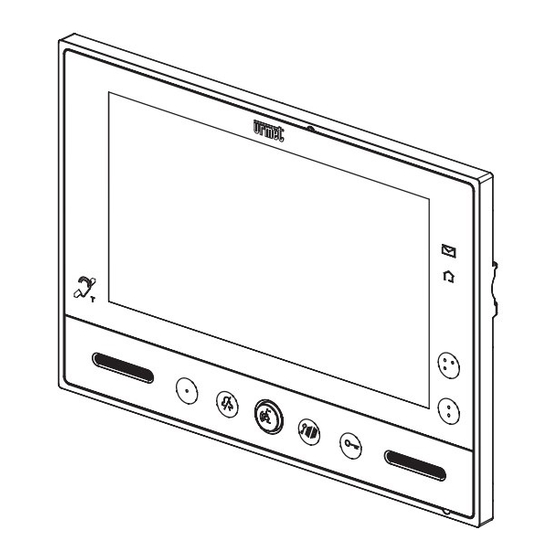
STRUTTURA VISTA FRONTALE VISTA POSTERIORE 10 9 Icona che indica che il videocitofono ha la ripetizione di fonia per gli audiolesi (ILA) Led verde di segnalazione presenza posta nella buca delle lettere (funzione LETTERBOX) Led blu di conferma trasmissione comando Yokis Pulsante per: –... -
Page 4: Installazione
INSTALLAZIONE • Fissare la staffa alla parete utilizzando una scatola Mod. 503 e le viti in dotazione o una scatola Ø 60 mm con viti adeguate. • Programmare i dip-switch e collegare alle morsettiere i conduttori dell’impianto. • Agganciare il videocitofono alla staffa in corrispondenza dei 4 ganci posti sui lati. •... -
Page 5: Sostituzione Del Videocitofono
SOSTITUZIONE DEL VIDEOCITOFONO Per la sostituzione del dispositivo occorre procedere secondo le seguenti indicazioni: • Sganciare il videocitofono dalla staffa di fi ssaggio, applicando una leva sulla linguetta posta nella parte inferiore per mezzo di cacciavite; • Rimuovere il videocitofono; •... -
Page 6: Segnalazione Stato Led
SEGNALAZIONE STATO LED STATO DI Stato ATTESA RIPOSO E PROGRAMMAZIONE SGANCIO RIPOSO IN FONIA TASTO (SOLO CON (ricezione VIDEOCITOFONO A PREMUTO chiamata) Pulsante RIPOSO) acceso acceso acceso spento spento verde fi sso verde fi sso verde fi sso spento spento spento spento spento... -
Page 7: Accesso Alla Modalità Di Programmazione
• MUTE (senza limiti di tempo): premendo il pulsante per un tempo breve il videocitofono sarà silenziato sino ad una successiva pressione sullo stesso pulsante. In seguito ad eventuale black out la funzione manterrà lo stato che aveva prima dell’evento. Quando la funzione “MUTE”... -
Page 8: Reset Impostazioni
RESET IMPOSTAZIONI Per ripristinare i parametri di default del dispositivo, dopo l’ingresso in programmazione, premere contemporaneamente i tasti e per più di 3 secondi; la conferma del comando avviene con l’emissione di 2 beep lunghi e l’uscita del dispositivo dallo stato di programmazione. CONFIGURAZIONE DEI DUE PULSANTI YOKIS CONFIGURAZIONE TRAMITE APP YOKIS PRO Il videocitofono VMODO Sch. - Page 9 Per confermare il collegamento, il LED del ricevitore 2 lampeggia una sola volta e il LED del ricevitore 1 smette di lampeggiare; a collegamento avvenuto i relè dei due ricevitori commutano una volta. Possibile con tutti Numero illimitato i ricevitori Yokis di ricevitori sul Bus Radio AUMENTO DELLA PORTATA PER MEZZO DI UN RICEVITORE INTERMEDIO...
-
Page 10: Funzione Di Ripetizione Di Chiamata Per Non Udenti Con Modulo Yokis
FUNZIONALITÀ DEL PULSANTE FUNZIONALITÀ MTR2000ERP MTV500ERP MVR500ERP Funzionalità 1* Accensione / spegnimento Variazione / spegnimento Salita / arresto / discesa Funzionalità 2 Memoria accensione Posizione intermedia Funzionalità 3 Accensione Accensione Salita / Arresto Funzionalità 4 Spegnimento Spegnimento Discesa / Arresto * Confi... -
Page 11: Caratteristiche Tecniche
230V ~ Prima di effettuare la programmazione, premere brevemente il pulsante P1 o P2 per 23 volte per sbloccare il relè, il modulo emetterà 3 lampeggi. Premere brevemente il pulsante P1 o P2 per 22 volte per 230V ~ programmare la modalità lampeggio, il modulo emetterà 2 lampeggi. -
Page 12: English
ENGLISH CONTENTS DESCRIPTION .............................. 12 STRUCTURE ..............................13 INSTALLATION ............................. 14 DESCRIPTION OF TERMINALS ....................... 14 REPLACING A VIDEO DOOR PHONE ...................... 15 BUTTON FUNCTIONS..........................15 LED INDICATING STATE ..........................16 OSD (ON SCREEN DISPLAY) MENU SETTINGS ..................16 MUTE FUNCTION ............................16 HOW TO ACCESS PROGRAMMING MODE.................... -
Page 13: Structure
STRUCTURE FRONT VIEW REAR VIEW 10 9 Icon indicating that the video door phone is hearing-aid compatible (ILA) Green mail in letterbox indication LED (LETTERBOX function) Blue Yokis command transmission confi rmation LED Button for: – sending activation/deactivation command channel 2 of the integrated Yokis transmitter –... -
Page 14: Installation
INSTALLATION • Fix the bracket to the wall using a box Mod. 503 and the screws provided or a Ø 60 mm box with suitable screws. • Program the dip-switches and connect the system wires to the terminal boards. • Couple the video door phone to the bracket at the four hooks on the sides. -
Page 15: Replacing A Video Door Phone
REPLACING A VIDEO DOOR PHONE Proceed as follows to replace a device: • Release the video door phone from the fi xing bracket, by levering on the tongue on the lower part by means of the screwdriver. • Remove the video door phone. •... -
Page 16: Led Indicating State
LED INDICATING STATE State STAND- RINGING PROGRAMMING BY AND ON-HOOK DURING AUDIO STATE (WITH VIDEO STAND-BY (receiving OPERATION BUTTON DOOR PHONE ON call) STAND-BY) PRESSED Button Green LED on Green LED on LED off Green LED on fi xed LED off fi... -
Page 17: How To Access Programming Mode
• MUTE (no time limit): by pressing the button for a short time the video door phone will be muted until the button is pressed again. After any power failure the function will keep the state it had before the event. When the “MUTE”... -
Page 18: Reset Settings
RESET SETTINGS To restore default parameters of the device after entering programming mode, hold buttons pressed for longer than 3 seconds. The system will beep twice times to confi rm and exit programming. CONFIGURATION OF THE TWO YOKIS BUTTONS CONFIGURATION VIA THE YOKIS PRO APP The VMODO video door phone Ref. - Page 19 To confi rm the connection, the LED of receiver 2 will blink once and the LED of receiver 1 will stop blinking. The relays of the two receivers will switch once when the connection has been established. Possible with all Unlimited number Yokis receivers of receivers on...
-
Page 20: Call Repeat Function For Hearing-Impaired Users With Yokis Module
BUTTON FUNCTION FUNCTIONS MTR2000ERP MTV500ERP MVR500ERP Function 1* Power on / off Change / off Up / stop / down Function 2 Memory on Intermediate position Function 3 Up / Stop Function 4 Down / Stop * Default confi guration To changing the function of a button: 1 - Briefl... -
Page 21: Technical Specifications
Before programming, briefl y press button P1 or P2 23 times to 230V ~ unlock the relay. The module will blink 3 times. Briefl y press button P1 or P2 22 times to program the blinking mode. The module will blink twice. 230V ~ Optional pushbuttons 3. -
Page 22: Français
FRANÇAIS SOMMAIRE DESCRIPTION .............................. 22 STRUCTURE ..............................23 INSTALLATION ............................. 24 DESCRIPTION DES BORNES ........................24 REMPLACEMENT DU MONITEUR ......................25 FONCTION DES BOUTONS ......................... 25 SIGNALISATION ETAT PAR LED ......................... 26 REGLAGES SUR LE MENU OSD (ON SCREEN DISPLAY) ................. 26 FONCTION MUTE ............................ -
Page 23: Structure
STRUCTURE VUE AVANT VUE ARRIERE 10 9 Icône indiquant que le moniteur est pourvu de la fonction de répétition de phonie pour les malentendants (ILA) verte indiquant présence courrier dans boîte lettres (fonction LETTERBOX) LED bleue confi rmant la transmission de la commande Yokis Bouton pour : –... -
Page 24: Installation
INSTALLATION • Fixer l’étrier à la paroi à l’aide d’un boîtier Mod. 503 et des vis fournies ou d’un boîtier Ø 60 mm avec des vis appropriées. • Régler les commutateurs et brancher les conducteurs de l’installation aux borniers. • Fixer le moniteur à... -
Page 25: Remplacement Du Moniteur
REMPLACEMENT DU MONITEUR Pour le remplacement du dispositif, procéder selon les instructions suivantes : • Pour décrocher le moniteur de l’étrier de fi xation, introduire la pointe d’un tournevis en faisant levier sur la languette située dans la partie inférieure ; •... -
Page 26: Signalisation Etat Par Led
SIGNALISATION ETAT PAR LED ETAT DE Etat ATTENTE REPOS ET PROGRAMMATION DECROCHAGE REPOS PHONIE TOUCHE (UNIQUEMENT SI (réception MONITEUR AU ENFONCEE appel) Bouton REPOS) LED verte allumée LED verte allumée LED verte allumée LED éteinte LED éteinte fi xe fi xe fi... -
Page 27: Acces Au Mode De Programmation
• MUTE (sans limite de temps) : en appuyant brièvement sur le bouton , le moniteur est mis en mode silencieux jusqu’à ce que le même bouton est enfoncé une deuxième fois. Suite à une coupure d’électricité, la fonction maintient toujours le même état. Lorsque la fonction «... -
Page 28: Remise A Zero Des Parametres
REMISE A ZERO DES PARAMETRES Pour rétablir les paramètres par défaut du dispositif, après l’accès à la programmation, appuyer en même temps sur les touches pendant plus de 3 secondes ; la commande sera confi rmée par l’émission de 2 bips sonores prolongés et par la sortie du dispositif de l’état de programmation. CONFIGURATION DES DEUX BOUTONS YOKIS CONFIGURATION PAR APP YOKIS PRO Le moniteur VMODO Réf. - Page 29 Pour confi rmer la connexion, la LED du récepteur 2 clignote une seule fois et la LED du récepteur 1 arrête de clignoter ; une fois la connexion établie, les relais des deux récepteurs commutent une fois. Possible avec tous Nombre illimité...
-
Page 30: Fonction De Répétition D'appel Pour Malentendants Avec Module Yokis
FONCTIONS DU BOUTON FONCTION MTR2000ERP MTV500ERP MVR500ERP Fonction 1* Mise sous / hors tension Variation / mise hors tension Montée / Arrêt / Descente Fonction 2 Mémoire mise sous tension Position intermédiaire Fonction 3 Mise sous tension Mise sous tension Montée / Arrêt Fonction 4 Mise hors tension... -
Page 31: Caracteristiques Techniques
Avant d’effectuer la programmation, appuyer brièvement 23 fois 230V ~ sur le bouton P1 ou P2 pour déverrouiller le relais ; le module clignotera 3 fois. Appuyer brièvement 22 fois sur le bouton P1 ou P2 pour programmer le mode de clignotement ; le module clignotera 2 fois. 230V ~ BP optionnels 3. -
Page 32: Español
ESPAÑOL ÍNDICE DESCRIPCIÓN ............................. 32 ESTRUCTURA .............................. 33 INSTALACIÓN .............................. 34 DESCRIPCIÓN DE LOS BORNES ......................34 SUSTITUCIÓN DEL VIDEOINTERFONO ....................35 FUNCIÓN DE LOS PULSADORES ....................... 35 INDICACIÓN ESTADO LED .......................... 36 REGULACIONES EN EL MENÚ OSD (ON SCREEN DISPLAY) ..............36 FUNCIÓN MUTE ............................ -
Page 33: Estructura
ESTRUCTURA VISTA DELANTERA VISTA TRASERA 10 9 Icono que indica que el videointerfono tiene la repetición de fonía para hipoacúsicos (ILA) Led verde de indicación de presencia de correspondencia en el buzón (función LETTERBOX) Led azul de confi rmación de transmisión de mando Yokis Pulsador para: –... -
Page 34: Instalación
INSTALACIÓN • Fijar el soporte en la pared utilizando una caja Mod. 503 y los tornillos entregados con el equipo, o una caja Ø 60 mm con los tornillos adecuados. • Programar los interruptores dip y conectar a los tableros de bornes los conductores del sistema. •... -
Page 35: Sustitución Del Videointerfono
SUSTITUCIÓN DEL VIDEOINTERFONO Para reemplazar el dispositivo se deben seguir estas indicaciones: • Descolgar el videointerfono del soporte de fi jación, haciendo palanca con un destornillador en la lengüeta presente en la parte inferior; • Retirar el videointerfono; • Enganchar el dispositivo nuevo en el soporte utilizando los ganchos presentes en los extremos. FUNCIÓN DE LOS PULSADORES ESTADO DE Estado... -
Page 36: Indicación Estado Led
INDICACIÓN ESTADO LED ESTADO DE Estado ESPERA DE REPOSO Y PROGRAMACIÓN RESPUESTA REPOSO EN FONÍA PULSADOR (SÓLO CON (recepción VIDEOINTERFONO ACCIONADO de llamada) Pulsador EN REPOSO) Led encendido Led encendido Led encendido Led apagado Led apagado verde fi jo verde fi jo verde fi... -
Page 37: Acceso Al Modo De Programación
Después de un posible corte de luz, la función conservará el estado que tenía antes del evento. Cuando la función “MUTE” está activa, también se desactivan todas las otras indicaciones acústicas (bips). ACCESO AL MODO DE PROGRAMACIÓN Para acceder al modo de programación del dispositivo, presionar y mantener accionado el pulsador durante un tiempo prolongado (más de 5 segundos) cuando el dispositivo está... -
Page 38: Configuración De Los Dos Pulsadores Yokis
CONFIGURACIÓN DE LOS DOS PULSADORES YOKIS CONFIGURACIÓN USANDO LA APLICACIÓN YOKIS PRO El videointerfono VMODO Ref. 1719/1 o 1719/2 está perfectamente integrado en la Aplicación instalador YOKIS PRO. Por lo tanto, es posible confi gurar sus dos pulsadores Yokis utilizando la aplicación, y luego descargar la confi... - Page 39 Posible con todos Número ilimitado los receptores Yokis de receptores en el Bus Radio AUMENTO DEL ALCANCE MEDIANTE UN RECEPTOR INTERMEDIO 1. Defi nir el “Bus Radio” entre los receptores como se describió más arriba. 2. Conectar el videointerfono al receptor que se quiere controlar, presionando brevemente 5 veces el pulsador seleccionado del videointerfono (E5).
-
Page 40: Función De Repetición De Llamada Para Sordos Con Módulo Yokis
FUNCIÓN DEL PULSADOR FUNCIÓN MTR2000ERP MTV500ERP MVR500ERP Función 1* Encendido / apagado Variación / apagado Subida / parada / bajada Función 2 Memoria de encendido Posición intermedia Función 3 Encendido Encendido Subida / Parada Función 4 Apagado Apagado Bajada / Parada * Configuración de fábrica Para modifi... -
Page 41: Características Técnicas
Antes de la programación, presionar brevemente 23 veces el 230V ~ pulsador P1 o P2 para desbloquear el relé; el módulo genera 3 parpadeos. Presionar brevemente 22 veces el pulsador P1 o P2 para programar el modo de parpadeo; el módulo genera 2 230V ~ parpadeos. -
Page 42: Deutsch
DEUTSCH INHALTSVERZEICHNIS BESCHREIBUNG ............................42 STRUKTUR ..............................43 INSTALLATION ............................. 44 BESCHREIBUNG DER ANSCHLUSSKLEMMEN ..................44 ERSETZEN DER VIDEOSPRECHANLAGE ....................45 TASTENFUNKTION ............................45 LED-STATUS- ANZEIGE ..........................46 EINSTELLUNGEN IM OSD- MENÜ (ON SCREEN DISPLAY) ............... 46 MUTE-FUNKTION ............................46 ZUGRIFF AUF DEN PROGRAMMIERMODUS ..................... -
Page 43: Struktur
STRUKTUR VORDERANSICHT RÜCKANSICHT 10 9 Symbol, das darauf hinweist, dass die Videosprechanlage mit der Gesprächsverstärkung für Hörbehinderte ausgestattet ist (ILA) Grüne Led zur Anzeige des Vorliegens von Post im Briefkasten (LETTERBOX-Funktion) Blaue Led zur Bestätigung der Übertragung des Yokis-Befehls Taste für: –... -
Page 44: Installation
INSTALLATION • Die Halterung an der Wand befestigen und dazu ein Gehäuse Mod. 503 und die im Lieferumfang enthaltenen Schrauben oder ein Gehäuse Ø 60 mm mit den entsprechenden Schrauben verwenden. • Den Dip-Schalter programmieren und die Leiter der Anlage an die Klemmenleisten anschließen. •... -
Page 45: Ersetzen Der Videosprechanlage
ERSETZEN DER VIDEOSPRECHANLAGE Zum Ersetzen des Geräts muss wie folgt vorgegangen werden: • Die Videosprechanlage aus der Halterung lösen, indem an der Lamelle im unteren Teil mit Hilfe eines Schraubendrehers gehebelt wird; • Die Videosprechanlage entfernen; • Das neue Gerät mit Hilfe der Haken an den Enden an der Halterung sichern. TASTENFUNKTION Status PROGRAMMIERSTATUS... -
Page 46: Led-Status- Anzeige
LED-STATUS- ANZEIGE Status PROGRAMMIERSTATUS RUHEMODUS WARTEZEIT (NUR MIT RUHEMODUS ABHEBEN GESPRÄCH IM GANG UND TASTE VIDEOSPRECHANLAGE (Rufeingang) GEDRÜCKT Taste IM RUHEMODUS) Led durchgehend Led durchgehend grün Led durchgehend Led ausgeschaltet ausgeschaltet grün eingeschaltet eingeschaltet grün eingeschaltet Led ausgeschaltet Led ausgeschaltet Led ausgeschaltet Led ausgeschaltet ausgeschaltet... -
Page 47: Zugriff Auf Den Programmiermodus
ZUGRIFF AUF DEN PROGRAMMIERMODUS Um in den Programmiermodus zu gelangen, die Taste betätigen und längere Zeit gedrückt halten (länger als 5 Sekunden), wenn das Gerät sich im Ruhemodus befi ndet. Der Zugriff auf den Programmiermodus wird von einem Ertönen von drei Beeps und der visuellen Signalisierung des MUTE-Symbols bestätigt, das zu blinken beginnt. -
Page 48: Konfiguration Der Beiden Yokis- Tasten
KONFIGURATION DER BEIDEN YOKIS- TASTEN KONFIGURATION ÜBER APP YOKIS PRO Die Videosprechanlage VMODO BN 1719/1 oder 1719/2 ist vollständig in die Installateur-App YOKIS PRO integriert. Es ist daher möglich, ihre beiden Yokis-Tasten über die App zu konfi gurieren und dann die Konfi... - Page 49 Mit allen Empfängern Unbegrenzte Anzahl von Yokis möglich von Empfängern auf Funkbus ERHÖHUNG DER REICHWEITE MIT HILFE EINES ZWISCHENEMPFÄNGERS 1. Defi nieren Sie den „Funkbus“ unter den Empfängern, wie zuvor beschrieben. 2. Verbinden Sie die Videosprechanlage mit dem Empfänger, der gesteuert werden soll, indem 5 Mal kurz auf die gewählte Taste der Videosprechanlage gedrückt wird (E5).
-
Page 50: Rufwiederholungsfunktion Für Gehörlose Mit Yokis-Modul
FUNKTIONWEISE DER TASTE FUNKTIONSWEISE MTR2000ERP MTV500ERP MVR500ERP Funktionsweise 1* Ein- / Ausschalten Änderung / Ausschalten Hochfahren / Stopp / Herunterfahren Funktionsweise 2 Speicher Einschalten Zwischenposition Funktionsweise 3 Einschalten Einschalten Hochfahren / Stopp Funktionsweise 4 Ausschalten Ausschalten Herunterfahren / Stopp * Werkseitige Konfi guration Um die Funktionsweise einer Taste zu ändern: 1 - Drücken Sie 10 Mal schnell auf eine beliebige Taste der Videosprechanlage (Konfigurationsmenü... -
Page 51: Technische Eigenschaften
Vor dem Ausführen der Programmierung kurz die Taste P1 oder 230V ~ P2 23 Mal betätigen, um das Relais zu entriegeln. Das Modul sendet 3 Blinkzeichen aus. Kurz die Taste P1 oder P2 22 Mal betätigen, um den Blinkmodus zu programmieren. Das Modul sendet 2 Blinkzeichen aus. 230V ~ Tastenoptionen 3. -
Page 52: Schema Di Collegamento
Esempio di centralizzazione di luci e tapparelle con videocitofono sch. 1719/1 o 1719/2 e moduli radio Yokis Example of centralisation of lights and shutters with video door phone Ref. 1719/1 or 1719/2 and Yokis radio modules Exemple de centralisation de l’éclairage et des volets roulants avec moniteur Réf. 1719/1 ou 1719/2 et modules radio Yokis Ejemplo de centralización de luces y persianas con videointerfono ref. - Page 53 ITALIANO DIRETTIVA 2012/19/UE DEL PARLAMENTO EUROPEO E DEL CONSIGLIO del 4 luglio 2012 sui rifi uti di apparecchiature elettriche ed elettroniche (RAEE) Il simbolo del cassonetto barrato riportato sull’apparecchiatura o sulla sua confezione indica che il prodotto alla fi ne della propria vita utile deve essere raccolto separatamente dagli altri rifi uti. L’utente dovrà, pertanto, conferire l’apparecchiatura giunta a fi...
- Page 54 ESPANOL DIRECTIVA 2012/19/UE DEL PARLAMENTO EUROPEO Y DEL CONSEJO del 4 de julio de 2012 sobre residuos de aparatos eléctricos y electrónicos (RAEE) El símbolo del contenedor de basura tachado con un aspa en el producto, o en su embalaje, indica que dicho producto no debe desecharse junto con los otros residuos domésticos.
- Page 55 DS1719-004...
- Page 56 DS 1719-004 LBT 20823 URMET S.p.A. Area tecnica 10154 TORINO (ITALY) servizio clienti +39 011.23.39.810 VIA BOLOGNA 188/C http://www.urmet.com Telef. +39 011.24.00.000 (RIC. AUT.) e-mail: info@urmet.com +39 011.24.00.300 - 323 MADE IN CHINA...
Need help?
Do you have a question about the modo 1719 and is the answer not in the manual?
Questions and answers