Chapters
Table of Contents

Related Manuals for urmet domus miro 1750


Summary of Contents for urmet domus miro 1750
- Page 1 Mod. 1750 DS1750-018 LBT20680 VIDEOCITOFONO PER SISTEMA COAX COAX SYSTEM VIDEO DOORPHONE MONITEUR SYSTÈME COAX VIDEOINTERFONO SISTEMA COAX KOAX-SYSTEM VIDEOSPRECHANLAGE Sch./Ref.1750/90...
-
Page 2: Table Of Contents
ITALIANO DESCRIZIONE ......................2 DESCRIZIONE DEI COMPONENTI ................3 INSTALLAZIONE ......................4 DESCRIZIONE DEI MORSETTI ..................5 FUNZIONAMENTO ....................... 6 RISPOSTA AD UNA CHIAMATA ................6 ATTIVAZIONE SERRATURA ELETTRICA ............... 6 IMPOSTAZIONI DEL VOLUME DELLA SUONERIA ..........6 CARATTERISTICHE TECNICHE .................. 6 ENGLISH ........................ -
Page 3: Descrizione Dei Componenti
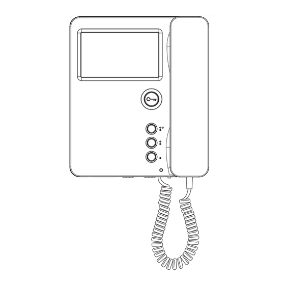
DESCRIZIONE DEI COMPONENTI 1. Tasto apriporta 2. Led verde presente sotto al tasto apriporta 3. Pulsante 4. Pulsante 5. Pulsante 6. LED rosso per indicazione del volume suoneria / MUTE 7. Connettori a 9 vie per il collegamento alla morsettiera 8. -
Page 4: Installazione
INSTALLAZIONE Fissare la staffa a parete utilizzando una scatola Mod. 503 e le viti in dotazione o una scatola Ø 60 mm con viti adeguate. Collegare alla morsettiera i fili provenienti dal videocitofono. Collegare i conduttori alla morsettiera. Agganciare il monitor alla staffa e bloccarlo avvitando le viti A di fissaggio. Scatola Mod. 503 Scatola Ø 60 mm (*) Nel caso di persone con disabilità o specifiche Scheda necessità di tipo D1 (con età avanzata), D2 morsettiere (con difficoltà motoria degli arti inferiori) e D3 (con difficoltà motoria degli arti superiori),... -
Page 5: Descrizione Dei Morsetti
DESCRIZIONE DEI MORSETTI Positivo di alimentazione videocitofono secondario Positivo alimentazione videocitofono Segnale video composito per collegamento entra-esci di un secondo videocitofono (se non presente inserire la resistenza da 75 Ohm spostando il jumper di terminazione) Massa segnale video Segnale video composito Negativo alimentazione videocitofono Accensione silenziosa del video Segnale di chiamata... -
Page 6: Funzionamento
FUNZIONAMENTO RISPOSTA AD UNA CHIAMATA A seguito di una chiamata da un posto esterno videocitofonico, il videocitofono squilla e visualizza l’immagine del visitatore. Agganciare la cornetta per attivare la comunicazione. L’attivazione della fonia è possibile solo con il display acceso. ATTIVAZIONE SERRATURA ELETTRICA In qualunque momento è... -
Page 7: English
ENGLISH DESCRIPTION ......................7 DESCRIPTION OF COMPONENTS ................8 INSTALLATION ......................9 DESCRIPTION OF TERMINALS ................. 10 OPERATION ......................11 ANSWERING A CALL ..................11 ELECTRIC LOCK ACTIVATION ................11 RINGTONE VOLUME SETTINGS ................11 TECHNICAL SPECIFICATIONS ................. 11 DESCRIPTION The main functions of the colour video door phone Ref.1750/90 are: •... -
Page 8: Description Of Components
DESCRIPTION OF COMPONENTS 1. Door opener button 2. Green LED under door opening button 3. Button 4. Button 5. Button 6. Red Led for call volume setting and MUTE 7. 9-Ways connectors for connecting to the terminal board 8. Jumper for inserting 75 Ohm terminal resistors 9. -
Page 9: Installation
INSTALLATION 1. Fix the bracket to the wall using a box Mod. 503 and the screws provided or a Ø 60 mm box with suitable screws. 2. Connect the wires from the video doorphone to the terminal board. Connect the system conductors to the terminal block. -
Page 10: Description Of Terminals
DESCRIPTION OF TERMINALS Secondary video door phone power positive Video door phone power positive Composite video signal for second video door phone in-out connection (insert the 75Ohm resistor by moving the terminal jumper, if not present) Video signal earth Composite video signal Video door phone power negative Silent video on Calling signal... -
Page 11: Operation
OPERATION ANSWERING A CALL After a call from a video door phone door unit, the video door phone will ring and the visitor’s image will appear. Hang off the handset to active the communication. Audio can only be activated with the display on. ELECTRIC LOCK ACTIVATION The electric lock connected to the door unit can be activated at any time by pressing the specific button RINGTONE VOLUME SETTINGS... -
Page 12: Français
FRANÇAIS DESCRIPTION ......................12 DESCRIPTION DES COMPOSANTS ................13 INSTALLATION ......................14 DESCRIPTION DES BORNES ..................15 FONCTIONNEMENT ....................16 REPONDRE A UN APPEL ..................16 ACTIVATION DE LA SERRURE ELECTRIQUE ............16 RÉGLAGES DU VOLUME DE SONNERIE ............16 CARACTÉRISTIQUES TECHNIQUES ................ -
Page 13: Description Des Composants
DESCRIPTION DES COMPOSANTS 1. Touche ouvre-porte 2. LED verte située sous la touche ouvre-porte 3. Bouton 4. Bouton 5. Bouton 6. LED rouge pour le réglage de la fonction MUTE et du volume des appels 7. Connecteurs à 9 voies pour la connexion au bornier 8. -
Page 14: Installation
INSTALLATION Fixer l’étrier à la paroi en utilisant un boîtier Mod. 503 et les vis livrées de série, ou bien un boîtier Ø 60 avec des vis appropriées. Connecter les fils du moniteur au bornier. Connecter les conducteurs au bornier. Accrocher le moniteur à l’étrier et le bloquer en vissant les vis de fixation A. Mod. 503 Ø 60 mm Boîtier Boîtier (*) Pour garantir le respect de la Directive de Carte des borniers référence pour les personnes handicapées (par... -
Page 15: Description Des Bornes
DESCRIPTION DES BORNES Positif d’alimentation du moniteur secondaire Positif d’alimentation du moniteur Signal vidéo composite pour le raccordement entrer-sortir d’un deuxième moniteur (si non présent, raccorder une résistance de 75 Ohm en déplaçant le cavalier de terminaison) Masse du signal vidéo Signal vidéo composite. -
Page 16: Fonctionnement
FONCTIONNEMENT REPONDRE A UN APPEL Suite à un appel d’une plaque de rue, le moniteur retentit et affiche l’image du visiteur. Accrocher le combiné pour activer la communication. L’activation de la phonie n’est possible qu’avec l’afficheur allumé. ACTIVATION DE LA SERRURE ELECTRIQUE A tout moment, il est possible d’activer la serrure électrique branchée au poste externe en appuyant sur la touche RÉGLAGES DU VOLUME DE SONNERIE •... -
Page 17: Español
ESPAÑOL DESCRIPCIÓN ......................17 DESCRIPCIÓN DE LOS COMPONENTES ..............18 INSTALACIÓN ......................19 DESCRIPCIÓN DE LOS BORNES ................20 FUNCIONAMIENTO ....................21 RESPUESTA A UNA LLAMADA ................21 ACTIVACIÓN DE LA CERRADURA ELÉCTRICA ..........21 CONFIGURACIÓN DEL VOLUMEN DEL TIMBRE ..........21 CARACTERÍSTICAS TÉCNICAS ................ -
Page 18: Descripción De Los Componentes
DESCRIPCIÓN DE LOS COMPONENTES 1. Tecla de apertura de la puerta 2. Led verde presente debajo de la tecla de apertura de la puerta 3. Pulsador 4. Pulsador 5. Pulsador 6. Led rojo para la configuración MUDO y volumen de llamada 7. Conectores de 9 vías para conectar al bloque de terminales 8. -
Page 19: Instalación
INSTALACIÓN Fijar el soporte de pared utilizando una caja Mod. 503 y los tornillos entregados con el equipo, o una caja Ø 60 con tornillos apropiados. Conectar los cables del videoportero al bloque de terminales. Conectar los conductores del sistema al bloque de terminales. -
Page 20: Descripción De Los Bornes
DESCRIPCIÓN DE LOS BORNES Positivo de alimentación del videointerfono secundario Positivo de alimentación del videointerfono Señal vídeo compuesto para conexión entrar-salir de un segundo videointerfono (si no está presente, conectar la resistencia de 75 Ohm desplazando el puente de extremo de línea) Masa de la señal vídeo Señal vídeo compuesto Negativo de alimentación del videointerfono... -
Page 21: Funcionamiento
FUNCIONAMIENTO RESPUESTA A UNA LLAMADA Tras una llamada de un microaltavoz videointerfónico, el videointerfono suena y muestra la imagen de la visita. Colgar el auricular para activar la comunicación. La activación de la fonía solo es posible con la pantalla encendida. ACTIVACIÓN DE LA CERRADURA ELÉCTRICA En cualquier momento se puede activar la cerradura eléctrica conectada al microaltavoz, pulsando el botón correspondiente... -
Page 22: Deutsch
DEUTSCH BESCHREIBUNG ....................... 22 BESCHREIBUNG DER BAUTEILE ................23 INSTALLATION ......................24 BESCHREIBUNG DER KLEMMEN................25 FUNKTIONSWEISE ....................26 RUFBEANTWORTUNG ..................26 AKTIVIERUNG DER ELEKTROVERRIEGELUNG ..........26 EINSTELLUNG DER RUFTONLAUTSTÄRKE ............26 TECHNISCHE DATEN ....................26 BESCHREIBUNG Die wichtigsten Leistungen der Farb-Videosprechanlage BN 1750/90 sind: •... -
Page 23: Beschreibung Der Bauteile
BESCHREIBUNG DER BAUTEILE 1. Türöffnertaste 2. Grüne Led unter der Türöffnertaste 3. Taste 4. Taste 5. Taste 6. Rote Led für Stummschaltung und Einstellung der Ruflautstärke 7. 9-Wege-Verbinder zum Anschließen des Klemmbrett 8. Jumper zum Einsetzen von 75 Ohm-Abschlusswiderständen 9. 8-Wege-Verbinder zum Anschließen des Klemmbretts 10. Helligkeit 11. Farbe 12. Befestigungsschrauben der Videoanlage an der Halterung 13. -
Page 24: Installation
INSTALLATION Anbauhalterung mit einer Einbaudose 503 und den beiliegenden Schrauben oder einer Runddose Ø 60 und entsprechenden Schrauben an der Wand befestigen. Die Drähte der Videosprechanlage an das Klemmbrett anschließen. Die Systemleiter an die Klemmleiste anschließen. Den Monitor an der Halterung anbringen und durch Verschrauben der Befestigungsschrauben A fixieren. -
Page 25: Beschreibung Der Klemmen
BESCHREIBUNG DER KLEMMEN Pluspol der sekundären Videosprechanlagenversorgung Pluspol Videosprechanlagenversorgung Composite-Videosignal für Ein-/Ausgangsschaltung einer zweiten Videosprechanlage (wenn nicht vorhanden, den 75 Ohm-Widerstand einsetzen, indem der End-Jumper versetzt wird) Erdanschluss des Videosignals Composite-Videosignal Minuspol Videosprechanlagenversorgung Leise Videoeinschaltung Rufsignal Mikrofonsignal Versorgungserdanschluss Lautsprechersignal Versorgungserdanschluss Türöffnertastensteuerung Hilfstastenklemmen Zur Aktivierung der elektrischen Lasten muss ein Relaiskasten... -
Page 26: Funktionsweise
FUNKTIONSWEISE RUFBEANTWORTUNG Im Anschluss an einen Anruf von einer Außenstelle der Videosprechanlage, klingelt die Videosprechanlage und blendet da Bild des Besuchers ein. Den Hörer einhängen, um das Gespräch zu aktivieren. Die Aktivierung des Gesprächs ist nur bei eingeschaltetem Display möglich. AKTIVIERUNG DER ELEKTROVERRIEGELUNG Die an die Außenstelle angeschlossene Elektroverriegelung kann jederzeit durch Betätigen der entsprechenden Taste aktiviert werden. - Page 27 ITALIANO DIRETTIVA 2012/19/UE DEL PARLAMENTO EUROPEO E DEL CONSIGLIO del 4 luglio 2012 sui rifiuti di apparecchiature elettriche ed elettroniche (RAEE) Il simbolo del cassonetto barrato riportato sull’apparecchiatura o sulla sua confezione indica che il prodotto alla fine della propria vita utile deve essere raccolto separatamente dagli altri rifiuti. L’utente dovrà, pertanto, conferire l’apparecchiatura giunta a fine vita agli idonei centri comunali di raccolta differenziata dei rifiuti elettrotecnici ed elettronici. In alternativa alla gestione autonoma è possibile consegnare l’apparecchiatura che si desidera smaltire al rivenditore, al momento dell’acquisto di una nuova apparecchiatura di tipo equivalente. Presso i rivenditori di prodotti elettronici con superficie di vendita di almeno 400 m è...
- Page 28 DS1750-018 LBT20680 URMET S.p.A. Area tecnica 10154 TORINO (ITALY) servizio clienti +39 011.23.39.810 VIA BOLOGNA 188/C http://www.urmet.com Telef. +39 011.24.00.000 (RIC. AUT.) e-mail: info@urmet.com +39 011.24.00.300 - 323 MADE IN CHINA...
Need help?
Do you have a question about the miro 1750 and is the answer not in the manual?
Questions and answers